Method for setting exact filling level of cooling medium in cooling circuit of a vehicle

A technology of cooling medium and cooling cycle, which is applied in the direction of engine cooling, slack regulator, machine/engine, etc., and can solve problems such as overfilling

Inactive Publication Date: 2010-10-13
VOITH PATENT GMBH
View PDF0 Cites 8 Cited by
  • Summary
  • Abstract
  • Description
  • Claims
  • Application Information

AI Technical Summary

Problems solved by technology

This creates the risk of overfilling the cooling circuit or coolant system of the motor vehicle

Method used


Image

  • Method for setting exact filling level of cooling medium in cooling circuit of a vehicle
  • Method for setting exact filling level of cooling medium in cooling circuit of a vehicle

Examples


Embodiment Construction

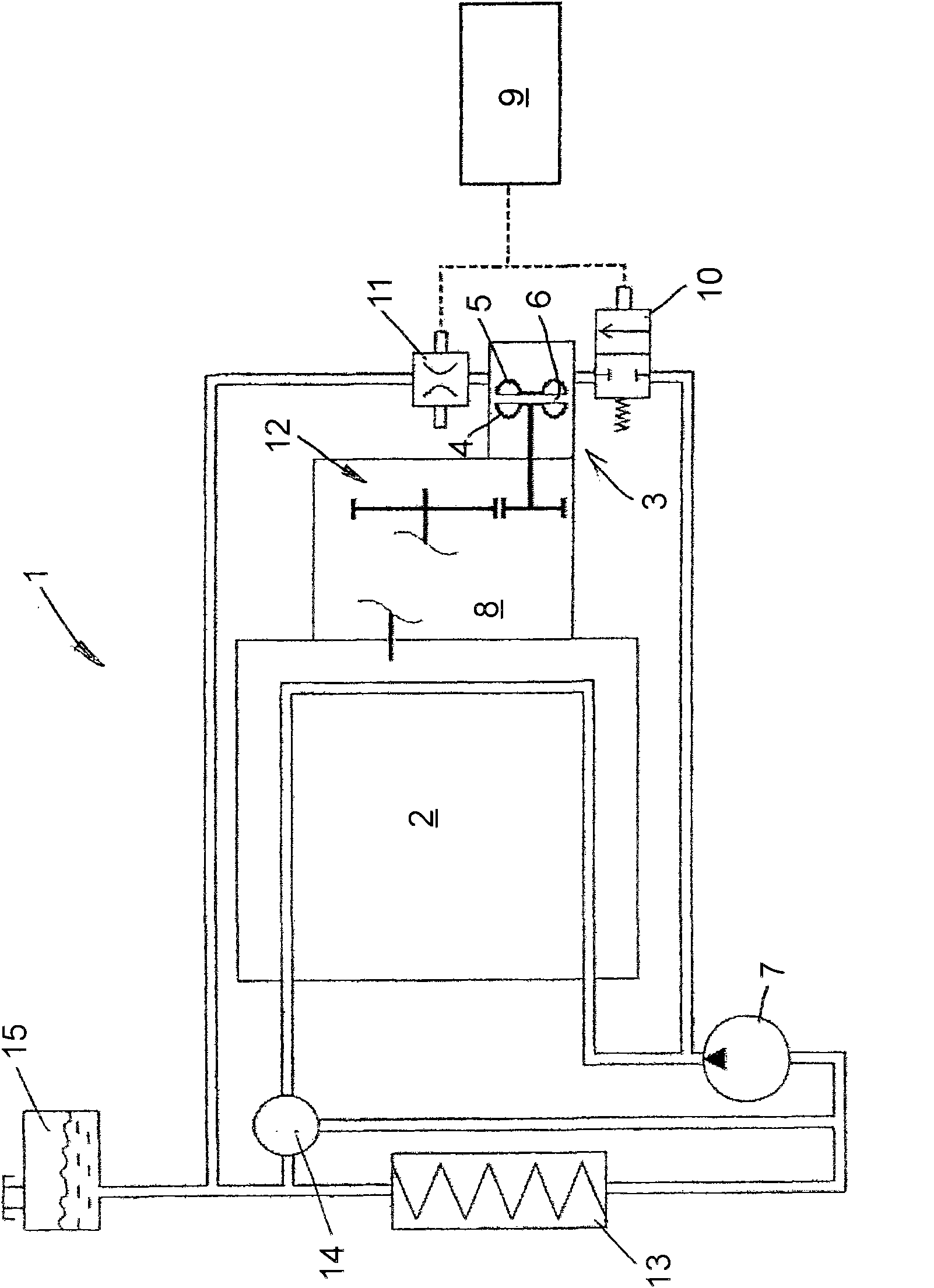
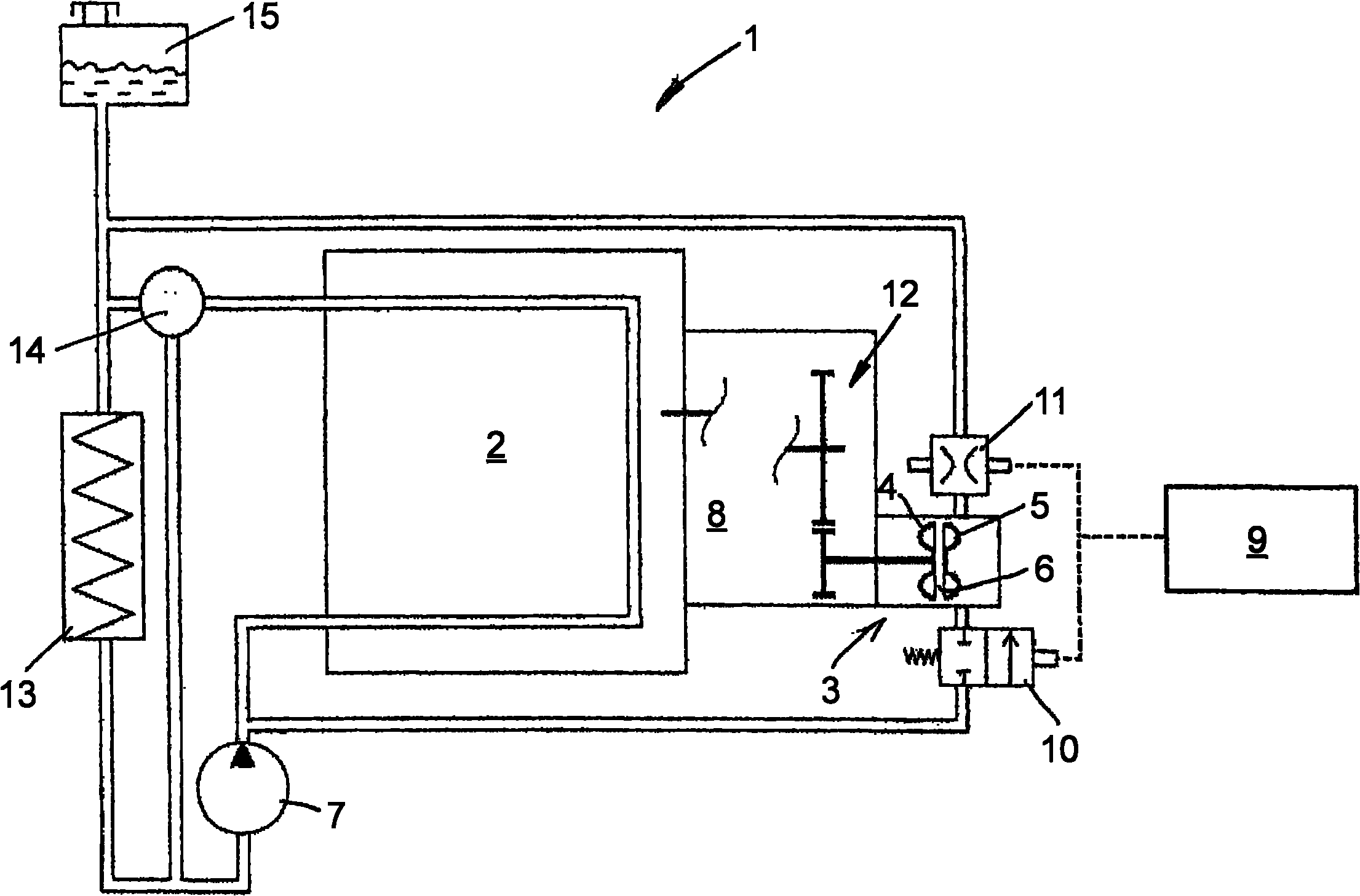
[0022] exist figure 1 A schematic diagram of a motor vehicle cooling circuit 1 according to a preferred embodiment is shown schematically in . A hydrodynamic retarder 3 is arranged in the cooling circuit 1 , comprising a main impeller 4 and a secondary impeller 5 , which form a torus-shaped working chamber 6 . The cooling medium of the cooling circuit 1 is simultaneously the working medium of the hydrodynamic retarder 3 . In this case, the secondary impeller 5 is designed to be stationary. Alternatively, the reducer 3 may also be designed as a counter-rotating reducer. The main impeller 4 is here driven in rotation by an auxiliary drive 12 of the transmission 8 , which is drivingly connected to the drive shaft of the drive motor 2 . The retarder 3 is therefore designed as a secondary retarder and brakes the motor vehicle depending on the driving speed. Alternatively, it is of course also possible to design the gear unit as a final gear unit and brake the motor vehicle as a...


PUM


Abstract

The present invention relates to a method for setting cooling medium distribution in a cooling circulation of motor vehicle, wherein, the circulation of cooling medium used for cooling a driving motor and / or other device is realized; wherein, a hydraulic retarder is provided in a cooling circulation and comprises a driven main impeller and a secondary impeller that commonly form an annular-surface-shaped operation chamber capable of being filled with or drained with operation medium selectively thereby transferring torque from the main impeller to the secondary impeller through hydraulic force; wherein, the cooling medium of the cooling circulation is simultaneously the operation medium of the hydraulic retarder; and the method comprises a step of: at the instant before the beginning and / or finishing of the stop process of motor vehicle, or the instant after the beginning and / or finishing of the stop process of motor vehicle or the period when the stop process of the motor vehicle begins and / or finishes, always completely or almost completely filling the operation chamber of the hydraulic retarder with operation medium.

Description

technical field [0001] The invention relates to a method for regulating the precise filling level of a coolant in a cooling circuit of a motor vehicle, in particular in a coolant storage tank, wherein a coolant circulates for cooling a drive motor and / or other devices. In this case, a hydrodynamic retarder is arranged in the cooling circuit, the working medium of which is the cooling medium of the cooling circuit. Background technique [0002] Cooling cycles of this type have been known several times in the prior art. Usually, for braking by means of a hydrodynamic retarder, part of the cooling medium circulated in the cooling circuit is introduced into the working chamber formed by the main impeller (rotor) and the secondary impeller (stator). Depending on the quantity of cooling medium (filling degree) that is present in the working chamber as working medium, the torque is transmitted more or less hydraulically from the main impeller to the secondary impeller, whereby the...

Claims


Application Information

Patent Timeline
Patent Type & Authority Applications(China)
IPC IPC(8): F01P11/18F16D57/00F16H57/04
CPCF16D65/78F16D57/04F01P11/0204B60T10/02
Inventor 迪特尔·劳克曼托马斯·盖尔
Owner VOITH PATENT GMBH
Why Eureka
Try Eureka