
Machine tool

A technology of machine tools and spindles, which is applied in the direction of turning equipment, tool holders, manufacturing tools, etc., can solve the problems of machine tool height increase, large-scale, complex structure of machine tool devices, etc., and achieve the effect of smooth transfer and easy cutting and processing

Inactive Publication Date: 2010-10-13
CITIZEN WATCH CO LTD
View PDF1 Cites 1 Cited by
  • Summary
  • Abstract
  • Description
  • Claims
  • Application Information

AI Technical Summary

Problems solved by technology

[0004] However, in the conventional machine tool described in Patent Document 1, when the semi-finished workpiece held and processed by one spindle is transferred to another spindle for cutting, although it is possible to transfer the workpiece between the first spindle and the second spindle through the back spindle However, in order to make the back spindle work, it is necessary to install the back spindle table, spindle motor, guide rail, etc., so there are problems such as complicated and large-scale device structure of the machine tool.
[0005] In addition, since the first tool post and the second tool post are arranged above and below the first spindle and the second spindle, respectively, there is a problem that the tool post installation space is wide in the vertical direction, so the overall height of the machine tool is increased.

Method used


Image

  • Machine tool
  • Machine tool
  • Machine tool

Examples


Embodiment Construction

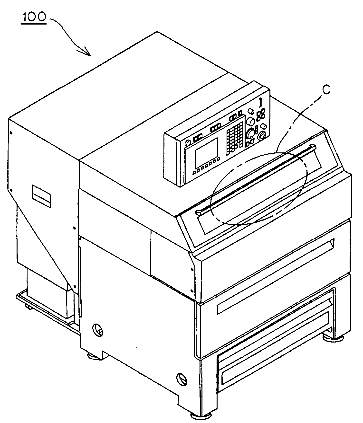
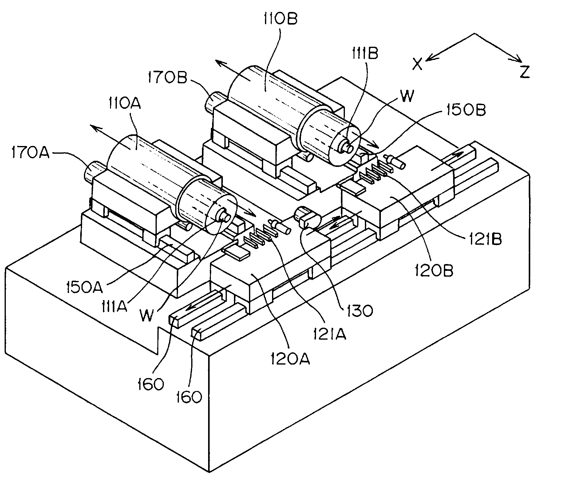
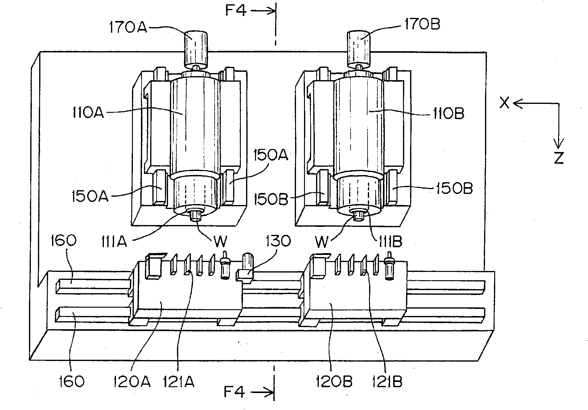
[0039] figure 1 The machine tool 100 of this embodiment is shown in part C, as Figure 2 to Figure 4 As shown, there are: a first headstock 110A that rotatably supports the first spindle 111A; and a second headstock 110B that rotatably supports the second spindle 111B.

[0040] The first headstock 110A and the second headstock 110B are arranged side by side in the left-right direction such that the axial direction of the first main shaft 111A is parallel to the axial direction of the second main shaft 111B. On one end face side of the first spindle 111A and the second spindle 111B, a clamper for gripping and holding the workpiece W is provided. The two main shafts 111A and 111B are arranged so that the end faces on the side of the holder face the same direction.

[0041] The first headstock 110A is slidably mounted on a rail 150A fixed to a base and extending in the Z-axis direction which is the axial direction of the two spindles 111A and 111B. The second headstock 110B i...


PUM


Abstract

The invention provides a machine tool which enhances work production efficiency while achieving compactness of the whole machine. In a machine tool (100) comprising a plurality of main shafts (111) and a plurality of tool rests (120), each tool rest (120) is arranged on the end face side of the main shaft (111), at least one of two adjoining tool rests (120) is provided with a work holding means (130) and the moving range of the tool rest (120) having the work holding means (130) is set to such a range that both main shafts (111) and the work holding means (130) reach a position where they face each other. Moving range of the tool rest (120) corresponding to the adjoining main shaft (111) is set to overlap the moving range of the tool rest (120) at least partially so that the tool rest (120) can slide to a position for avoiding mutual collision of the tool rests (120).

Description

technical field [0001] The invention relates to a machine tool for machining workpieces. Background technique [0002] A known conventional machine tool has: a first main shaft and a second main shaft, which are arranged in parallel with each other at a predetermined interval; a first tool post and a second tool post, which correspond to the above-mentioned first main shaft and the second main shaft; The main shaft is disposed opposite to the first main shaft and the second main shaft, and is relatively movable in a direction connecting the axes of the two main shafts and in a direction of approaching or separating from the two main shafts. (For example, refer to Patent Document 1). [0003] Patent Document 1: Japanese Patent Application Laid-Open No. 8-112738 (claims, image 3 ) [0004] However, in the conventional machine tool described in Patent Document 1, when the semi-finished workpiece held and processed by one spindle is transferred to another spindle for cutting,...

Claims


Application Information

Patent Timeline
IPC IPC(8): B23B3/30B23B15/00B23B21/00B23B29/24
CPCB23Q7/045B23Q39/04B23Q41/02B23B3/30
Inventor 粕谷浩史
Owner CITIZEN WATCH CO LTD
Learn More