Hydraulic drive, particularly of a digger, particularly for a rotation system

The technology of a driving device and a slewing device is applied in the field of hydraulic drive devices especially for excavators, especially for slewing devices, and can solve problems such as waste

Inactive Publication Date: 2010-10-13
LIEBHERR FRANCE
View PDF0 Cites 15 Cited by
  • Summary
  • Abstract
  • Description
  • Claims
  • Application Information

AI Technical Summary

Problems solved by technology

But in practice, the energy is actually not needed when it is available, so it is wasted

Method used


Image

  • Hydraulic drive, particularly of a digger, particularly for a rotation system
  • Hydraulic drive, particularly of a digger, particularly for a rotation system
  • Hydraulic drive, particularly of a digger, particularly for a rotation system

Examples


Embodiment Construction

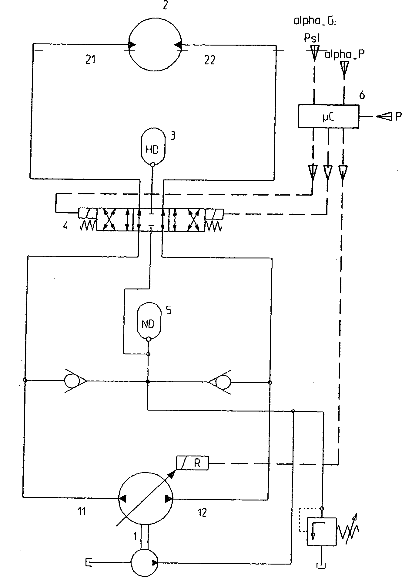
[0052] figure 1 The table shows a first embodiment of the hydraulic drive device according to the invention, in this embodiment, during the braking phase of the slewing device, in the first energy storage mode according to the invention, the energy from the braking can be stored in the high pressure In the accumulator 3, and when the slewing device is accelerated again, this energy can be given back to the drive device in the first recuperation mode, so that the diesel engine can be dimensioned correspondingly smaller.

[0053] The hydraulic drive according to the invention in the first embodiment now comprises a pump 1 and a motor 2 , here a variable axial piston pump and a constant displacement hydraulic motor, each of which has two delivery directions. The high-pressure accumulator 3 can communicate with the left side 11 of the pump 1 at the right side of the valve 4 through the valve 4 (here, a 6 / 3 valve, a three-position six-way valve), and communicate with the pump at th...


PUM


Abstract

The present invention relates to a hydraulic drive, particularly of a digger, particularly for a rotation system having a hydraulic circuit comprising a pump (1) and a motor (2), wherein a high-pressure reservoir (3) connectable to the pump and/or motor via at least one valve (4) and a control unit (6) controlling the at least one valve are provided.

Description

technical field [0001] The invention relates to a hydraulic drive, in particular for an excavator, in particular for a slewing device, which has a hydraulic circuit comprising a pump and a motor. Background technique [0002] The basic functions of the hydraulic drive of the excavator are the equipment movement completed by the hydraulic cylinder drive device, the travel movement of the excavator and the upper frame rotation movement completed by the hydrostatic rotary drive device. The hydraulic energy for this will be provided by one or more pumps which in turn are driven by an internal combustion engine, especially a diesel engine. In this case, a pump transfer case is used between the internal combustion engine and one or more pumps for equipment and travel movements. Furthermore, a separate pump can be used especially for the swivel movement of the upper frame. [0003] Thermal energy that heats the hydraulic fluid that occurs in addition to the hydraulic energy will ...

Claims


Application Information

Patent Timeline
Patent Type & Authority Applications(China)
IPC IPC(8): E02F9/22E02F9/12B66C23/86
CPCB60K6/12E02F9/2217E02F9/128Y02T10/6208F16H61/4096E02F9/123E02F9/2296Y02T10/62
Inventor F·L·赫尔布林
Owner LIEBHERR FRANCE
Why Eureka
Try Eureka