
Low-voltage electrical appliance life test device based on AC solid-state simulated load

A technology of low-voltage electrical appliances and test devices, which is applied in the direction of measuring devices, measuring device shells, instruments, etc., can solve the problem of single test current setting, reduce test power consumption, reduce test cost and equipment space, and have good versatility and The effect of flexibility

Pending Publication Date: 2019-01-25
HEBEI UNIV OF TECH
View PDF0 Cites 6 Cited by
  • Summary
  • Abstract
  • Description
  • Claims
  • Application Information

AI Technical Summary

Problems solved by technology

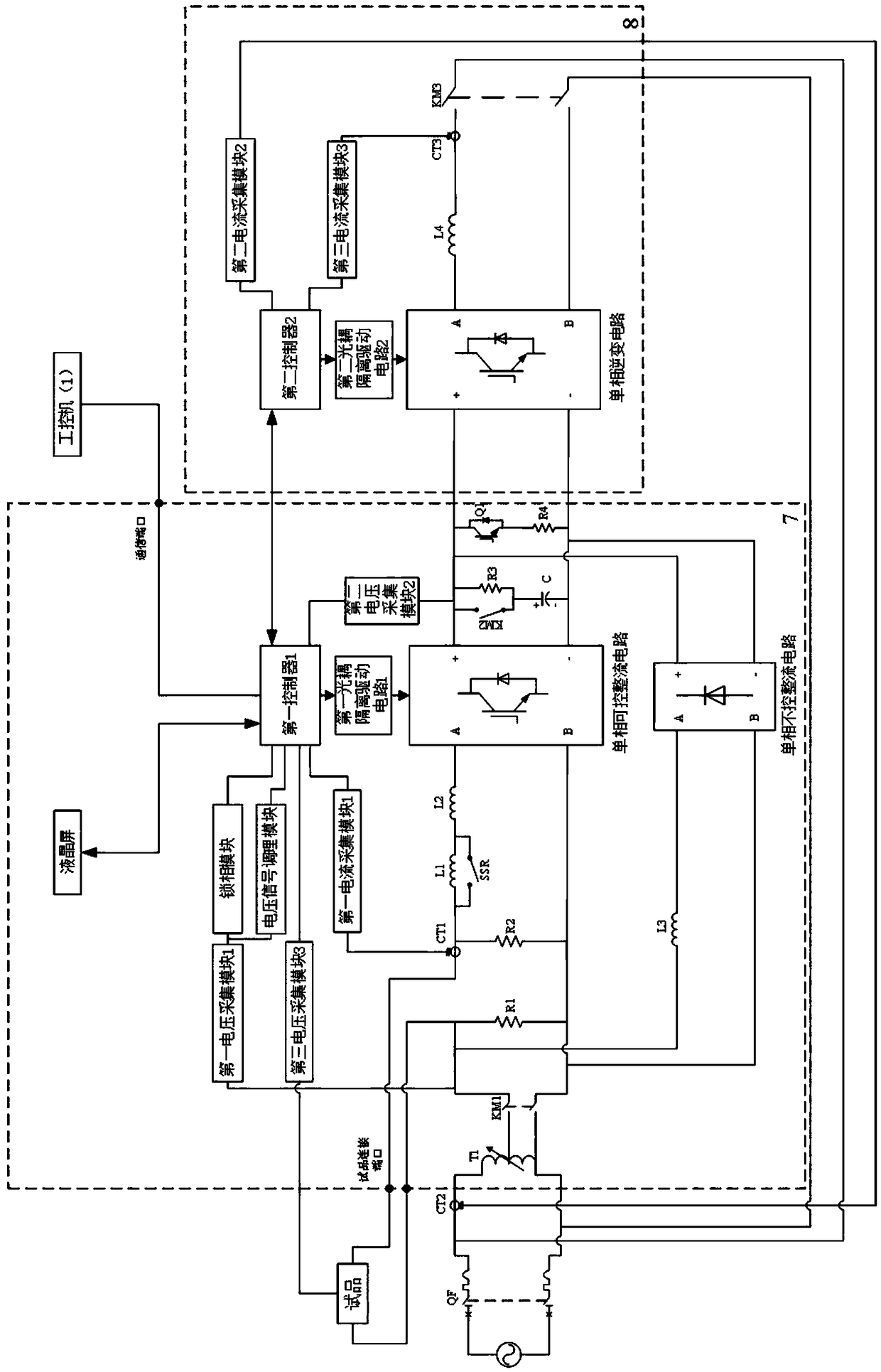
At the same time, the present invention designs the test product contact voltage and current acquisition loop, effectively detects the test product contact terminal voltage and the test product contact test current, and judges the action state of the test product contact in real time to control the flow through the test product during the action. The current of the product contact can simulate the actual situation more realistically and protect the test device at the same time; at the same time, the device can generate a test current of any shape, which is more suitable for controlling the actual load, and overcomes the shortcomings of the traditional test current setting and limited change

Method used


Image

  • Low-voltage electrical appliance life test device based on AC solid-state simulated load
  • Low-voltage electrical appliance life test device based on AC solid-state simulated load
  • Low-voltage electrical appliance life test device based on AC solid-state simulated load

Examples


Embodiment 1

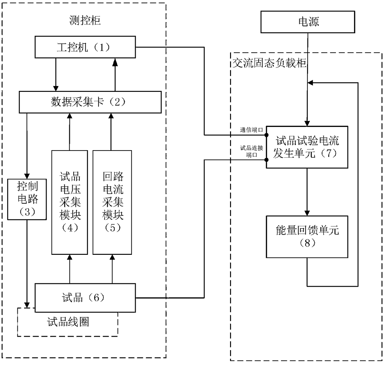
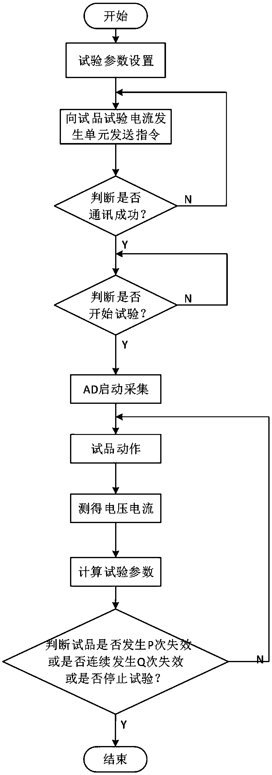
[0068] Carry out the electric life test of AC relay according to the control flow chart described above and the device of the present invention: choose AC relay sample, AC relay rated voltage is 220V, and rated current is 10A; Open industrial computer LabVIEW operating platform, according to AC relay voltage parameter Set the test frequency to 1800 times / h, the on-off duty ratio to 50%, the voltage of the test product to 220V, the test current given value I(t): the impulse current is 50A, the impulse current time is 250ms, the rated current is 10A, the rated current time 750ms, power factor is 0.7, DC bus voltage is 400V-410V; adjust single-phase voltage regulator T1 to 220V; AC solid state load cabinet is powered on, pre-charging is completed, wait for the start command, and the energy feedback unit starts running; LabVIEW operating platform Click After confirming, send the set parameter information to the AC solid-state load cabinet through the serial port; if the setting is ...


PUM


Abstract

The invention relates to a low-voltage electrical appliance life test device based on an AC solid-state simulated load. The low-voltage electrical appliance life test device comprises a measuring andcontrolling cabinet and an AC solid-state load cabinet, wherein the measuring and controlling cabinet is composed of an industrial control computer, a data acquisition card, a control circuit, a sample voltage acquisition module and a loop current acquisition module; the industrial control computer is connected with a data acquisition card; the control circuit, the sample voltage acquisition module and the loop current acquisition module are connected with the data acquisition card respectively; an input end of the sample voltage acquisition module is connected with two ends of a contact of the sample, and the output end of the module is connected with an AD input end of the data acquisition card; the input of the loop current acquisition module is a sample test current, and an output endis connected with the AD input end of the data acquisition card; and the AC solid-state simulated load comprises a sample test current generating unit and an energy feedback unit. The low-voltage electrical appliance life test device can generate the test currents in any shape, is more suitable for controlling the actual load, and overcomes the shortcoming of limitations of the conventional test current.

Description

technical field [0001] The invention relates to the fields of electric life test and power electronics, specifically designs a low-voltage electrical life test device based on an AC solid load, and designs an AC solid analog load by using power electronics technology. Background technique [0002] In the electrical life test of AC low-voltage electrical products, in order to simulate the actual controlled load, a combination of resistors and inductors is usually used to realize resistive and resistive-inductive test loads. This test load is called a simulated load. Traditional loads have the following problems: First, they are bulky and expensive. In order to meet the test requirements of multi-standard test products and enhance the versatility of the equipment, the traditional simulated load needs to be designed as a series-parallel combination of multiple resistors and inductors to meet the adjustment requirements. Even if the optimal design is adopted, the shortcomings o...

Claims


Application Information

Patent Timeline
IPC IPC(8): G01R31/00G01R1/04
CPCG01R1/04G01R31/00
Inventor 杜太行孙曙光刘旭林江春冬郝立林纪学玲王佳兴
Owner HEBEI UNIV OF TECH
Learn More