
Wheel and axle bending fatigue test device

A bending fatigue and test device technology, which is applied in measuring devices, railway vehicle testing, and material strength testing using a stable bending force. It can meet the needs of less research and other problems, and achieve the effect of reducing processing costs and improving the quality of railway trains

Pending Publication Date: 2019-12-31
CHANGCHUN UNIV OF TECH
View PDF0 Cites 5 Cited by
  • Summary
  • Abstract
  • Description
  • Claims
  • Application Information

AI Technical Summary

Problems solved by technology

[0003] The study found that when the railway train is running on the track, the wheel-rail contact surface will bear a large load, and there are various complex rigid motions such as rigid rolling, lateral sliding, longitudinal sliding, and spinning between the wheel and rail, which will easily lead to wheel Fatigue damage on the contact surface of the rail, and due to the load generated by the carriage during operation, bending fatigue damage is prone to occur at the axle position [1]
In the research of related fatigue test devices, most of them analyze the fatigue damage of the test piece, and there are few studies on whether the performance of the test device can meet the requirements.
There are also some studies on fatigue test equipment that only improve the performance of a certain aspect

Method used


Image

  • Wheel and axle bending fatigue test device
  • Wheel and axle bending fatigue test device
  • Wheel and axle bending fatigue test device

Examples


Embodiment Construction

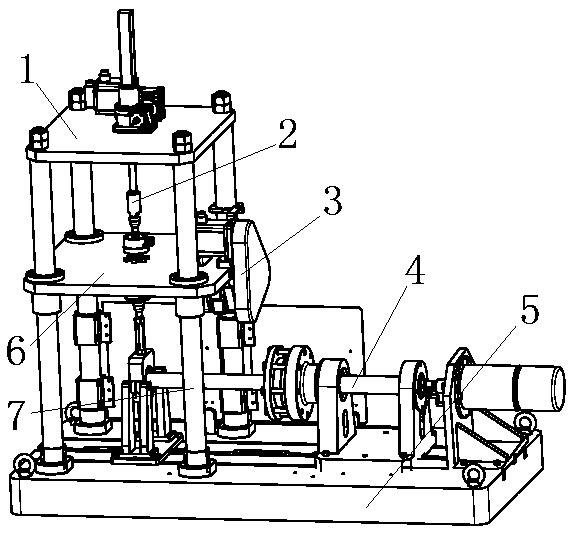
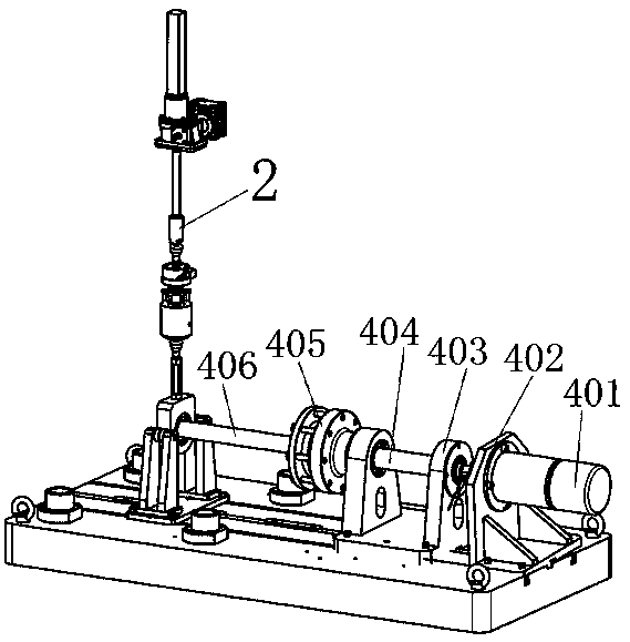
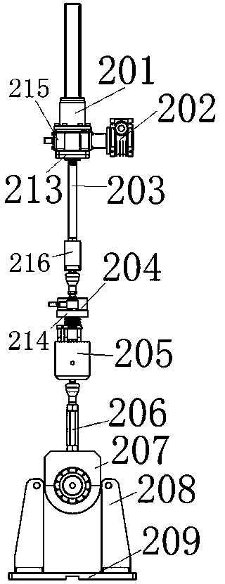
[0020] In the present invention, four pillars 7 arranged in a rectangular shape are fixed on one side of the bearing platform 5. The bearing platform 5 is a connector that is conveniently fixed or installed on other fixed equipment, and also carries all the mechanisms of the present invention. As a whole, the four pillars 7 play a supporting role, leaving space therebetween to facilitate the cooperation of other components in the movement space. The main components of the present invention are mainly divided into three parts: a longitudinal loading mechanism 2, a lateral movement mechanism 3 and a rotation mechanism 4, through which the corresponding forces are applied to test the three factors of longitudinal, lateral and rotation; The top supporting plate 1 is fixedly installed on the upper end of the root pillar 7, and the middle supporting plate 6 is installed in the middle; The lateral movement mechanism 3 is installed on the lower side of the support plate 6 through rail...


PUM


Abstract

A wheel and axle bending fatigue test device belongs to the technical field of test equipment. The object of the invention is to design a railway train wheel and axle bending fatigue test device by analyzing the actual operating conditions of the railway train and comprehensively considering various factors. According to the invention, four pillars arranged in a rectangular arrangement are fixed on one side of a bearing platform, the upper ends of the four pillars are fixedly installed with a top support plate, and a middle support plate is installed in the middle; a vertical loading mechanismis installed on the top support plate through an upper fixing member, and installed on the middle support plate through a lower fixing member; a lateral movement mechanism is installed under the middle support plate through the track, and the rotation mechanism is inserted into the inner bearing of the rotation bearing through the front end shaft. The invention realizes two kinds of fatigue teststhrough a fatigue test device, ensures that the test device can perform tests according to actual operating conditions, reduces the processing cost of the experimental device, and has a positive effect on improving the quality of China's railway trains.

Description

technical field [0001] The invention belongs to the technical field of test equipment. Background technique [0002] As an important means of transportation in rail transportation, railway trains have strict regulations and requirements for their design. Due to the high speed of railway trains, and with the continuous increase of train speed, there will be certain damage to the wheels and axles during operation. When the wheels or axles are damaged, it will directly affect the safety of railway transportation. In the operation of railway trains, the wheels not only have to bear the longitudinal load of the carriage, but also are affected by the lateral load due to the impact of shaking or the route, which has a lot of wear on the wheels and axles of the railway train. When the fatigue limit is reached When there is damage, it will cause great harm to the safety of the railway train and the personal safety in the car. For this reason, it is necessary to perform fatigue test...

Claims


Application Information

Patent Timeline
Patent Type & Authority Applications(China)
IPC IPC(8): G01M17/10G01N3/20G01N3/38
CPCG01M17/10G01N3/20G01N3/38G01N2203/0023G01N2203/0073
Inventor 王晓东郭富杰张明星严有权石铁山
Owner CHANGCHUN UNIV OF TECH
Learn More