
Tripod head

A cloud platform and bearing shell technology, applied in the field of cloud platform, can solve the problem of difficult operation of the platform, and achieve the effects of easy operation, high load and damage prevention

Active Publication Date: 2010-10-13
MK测量技术有限公司
View PDF8 Cites 12 Cited by
  • Summary
  • Abstract
  • Description
  • Claims
  • Application Information

AI Technical Summary

Problems solved by technology

Because the quick-release plate is still fixed in the base in the open position and because the rocker also needs to be twisted in order to fix the quick-release plate in the base, the known heads are very difficult for a single operator to operate, especially when the When a person wants to fasten a heavy optical instrument on a pan head known from DE 27 47 677 A1

Method used


Image

  • Tripod head
  • Tripod head
  • Tripod head

Examples


Embodiment Construction

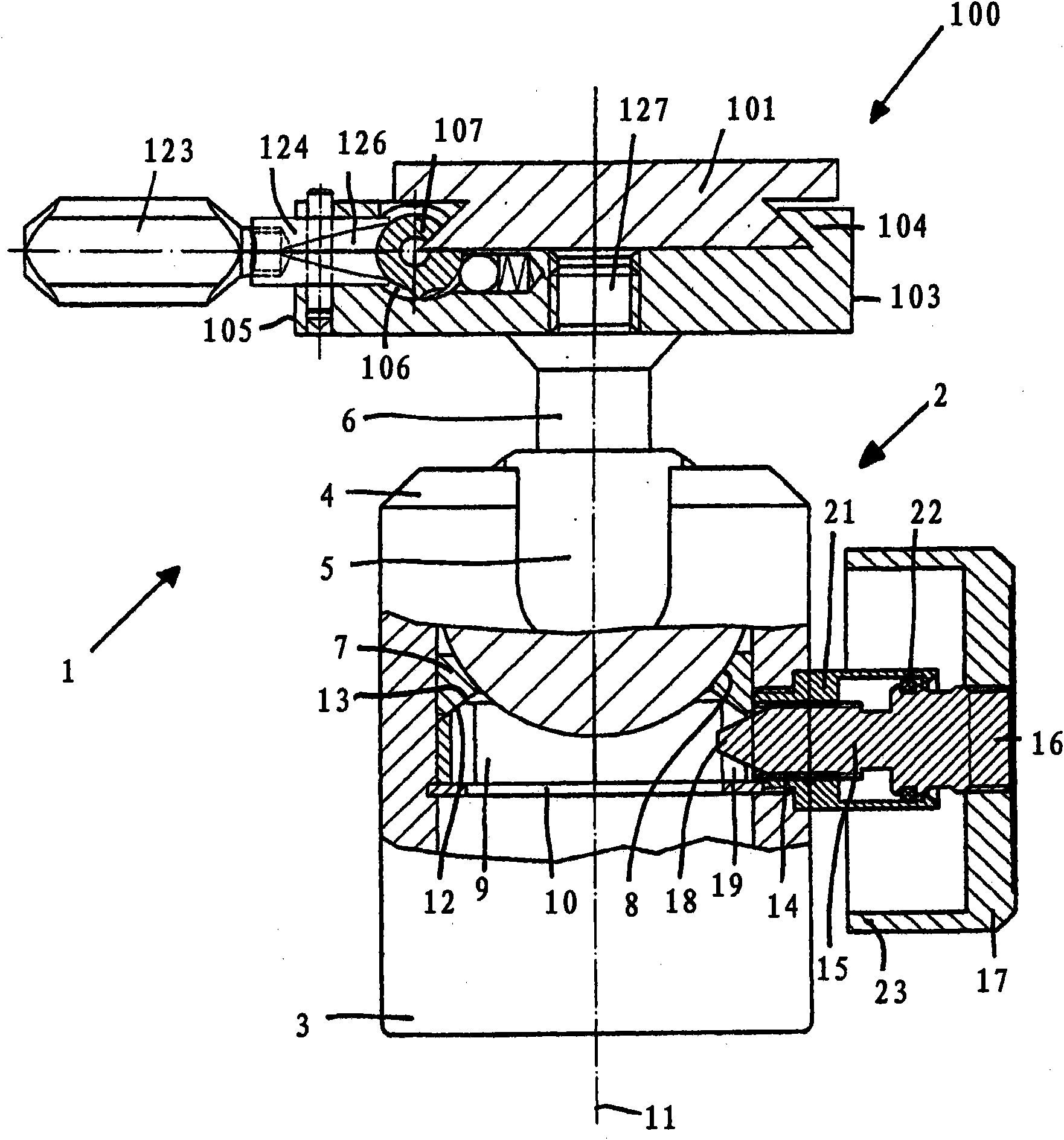
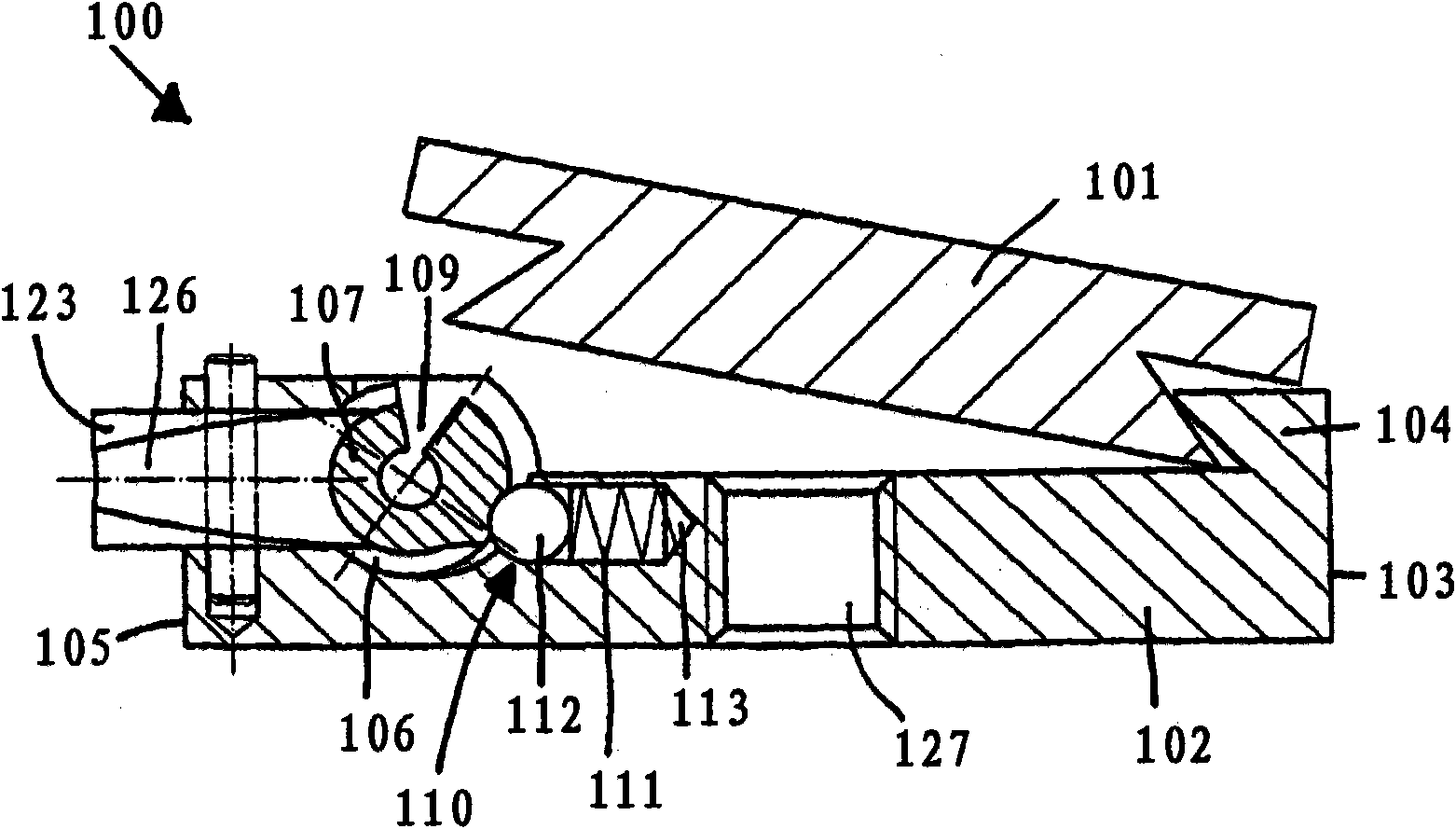
[0026] figure 1 Shown is a head generally designated 1 , which has a tilting device 2 and a holding device 100 fastened to the tilting device, said holding device having a quick-release plate 101 .

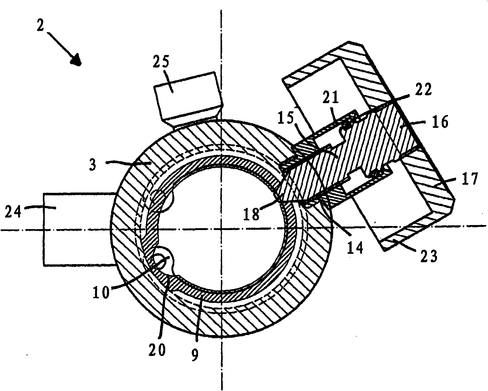
[0027] The tilting device 2 has an approximately cylindrical bearing housing 3 which is designed as a hollow cylinder. Provided at its upper end 4 is a flange, not visible in the drawing, directed inwards at right angles, which forms an upper bearing bush for a ball joint. Also arranged on the flange is a sliding bearing, likewise not visible in partial section, which has a preferably spherical sliding surface and cooperates with a ball joint 5 .

[0028] The ball joint 5 has a threaded straight projection 6 in the axial direction of the bearing housing 3, on which a payload can be fastened. Arranged below the ball joint 5 is a further axially displaceable slide bearing 7 , which has a spherical bearing surface 8 adapted to the ball joint 5 . Next to the sliding bearing 7 is a ...


PUM


Abstract

The invention relates to a tripod head having an inclination apparatus (2) having a universal joint (5) and having a holding apparatus (100), which can be secured on the universal joint, for holding a camera, a pair of binoculars, a spotting scope or such an optical instrument with a removable disk (101).

Description

technical field [0001] The invention relates to a platform with a tilting device having a ball joint with a ball joint mounted pivotably in a bearing housing, the ball joint being mounted in two ball joints in the bearing housing Between two sliding bearings, one of the sliding bearings is axially movably installed in the bearing housing toward the spacing direction of the sliding bearings, wherein the ball joints are arranged between the connecting discs located on the ends of the platform facing away from each other, one of which is One connection pad is connected or connectable to a camera, telescope, scope or similar optical instrument, while another connection pad is connected or connectable to at least one tripod leg or similar support. Background technique [0002] Such a tilting unit is known from German patent application 10 2006 001 580 A1. However, the axially displaceable slide bearing is only supported at one point by a conical pin. Due to the small contact su...

Claims


Application Information

Patent Timeline
IPC IPC(8): F16M11/04F16M11/14
CPCF16M11/14F16M11/041G03B17/56F16M11/04F16C11/106F16M11/16G03B17/566Y10T403/32745
Inventor W·比尔克林
Owner MK测量技术有限公司
Learn More