A burner, specifically a premix burner

A burner, premixing technology, applied in burners, burners, gas fuel burners, etc., can solve problems such as structural complexity

Inactive Publication Date: 2010-10-13
意大利精密机械技术股份公司
View PDF0 Cites 7 Cited by
  • Summary
  • Abstract
  • Description
  • Claims
  • Application Information

AI Technical Summary

Problems solved by technology

[0007] A major limitation of the known constructions described above is the structural complexity resulting from the number of parts required for the burner assembly

Method used


Image

  • A burner, specifically a premix burner
  • A burner, specifically a premix burner
  • A burner, specifically a premix burner

Examples


Embodiment Construction

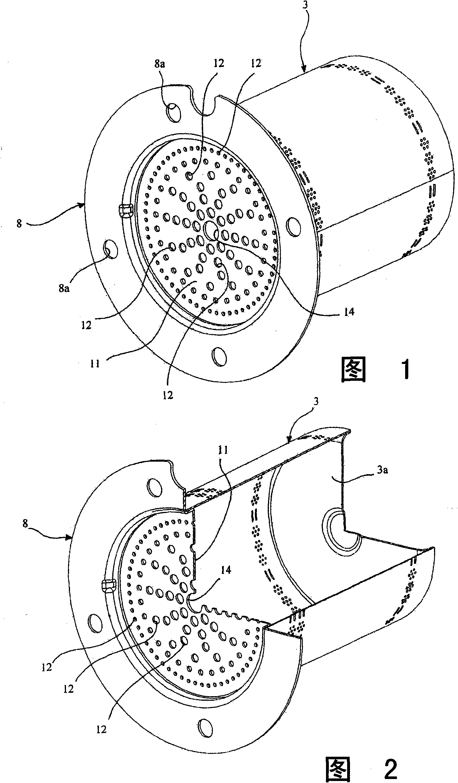
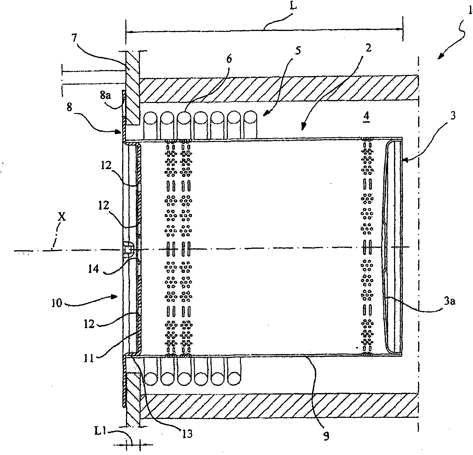
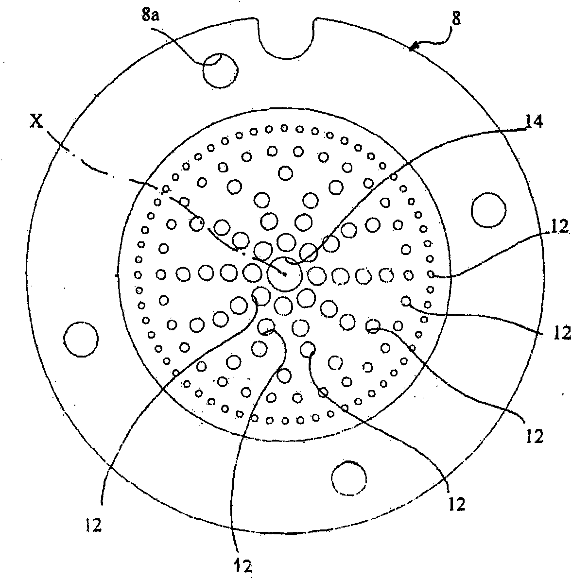
[0017] Referring to the accompanying drawings, reference number 1 designates the burner manufactured according to the present invention as a whole, in particular, a burner for premixed combustible gas.

[0018] The burner comprises a burner body 2 with a burner head 3 in which an air and gas mixture supplied to the burner is combusted, eg by means of fan means (not shown).

[0019] The burner is designed to be accommodated in a combustion chamber 4 of a heating device (not shown), which is shown only schematically, and a heat exchanger 5 is also accommodated in the combustion chamber, which is provided with a tube bundle 6, the working fluid in The tube bundle is circulated and heated by means of burners.

[0020] The burner body 2 is fixed to a shutter element 7 provided to seal the combustion chamber, which is removably connected to the stationary structure of the combustion chamber. Reference numeral 8 designates a connecting flange that fixes the burner body to the gate, ...


PUM


Abstract

A burner, particularly for combustible gas with premixing, comprises a cylindrical burner head (3) designed to be housed in a combustion chamber (4) of a heating apparatus, on which an air and gas mixture supplied to the combustion chamber (4) is burnt, the head (3) including a cylindrical shell (9) with through apertures, fixed at a first axial end by a connecting flange (8) to a shutter element (7) intended to seal the combustion chamber (4), while its opposite axial end has a solid end wall (3a) which seals the head (3), an element (10) for distributing the air and gas mixture, positioned inside the burner head (3) and intended to distribute the flow of combustible mixture reaching the burner on to the burner head (3). The distributor element comprises a platelike portion (11) extending as a continuation of said connecting flange (8) and extending substantially in an orthogonal direction to the axial direction of extension of the cylindrical head, the platelike portion (11) having through apertures (12) for distributing the mixture to the burner head (3).

Description

technical field [0001] The invention relates to a burner, in particular a premixed gas burner, having the features stated in the preamble of independent claim 1 . Background technique [0002] In this particular technical field, there is known a method of manufacturing a premixed gas burner whose burner head is designed to be housed in the combustion chamber in a position facing the heat exchanger, when the heat exchanger is fired by the burner flame Upon contact, the heat exchanger heats the fluid flowing through it. Typically, the burner is connected to a gate or similar element to seal the combustion chamber. [0003] In known burners of the type mentioned above, the burner head of the burner is made in the shape of a cylinder which extends into a combustion chamber which is also cylindrical, the two cylinders being preferably coaxial with each other. In this construction, the cylindrical shell of the burner head is provided with through holes designed to allow the pass...

Claims


Application Information

Patent Timeline
Patent Type & Authority Applications(China)
IPC IPC(8): F23D14/10F23D14/70
CPCF23D14/105F23D2900/00003F23D2203/1012F23D14/70F23D2210/00
Inventor G·斯科里巴诺M·贝格
Owner 意大利精密机械技术股份公司
Why Eureka
Try Eureka