Continuous reversible precision sawing machine

A precision sawing machine and sawing technology, which is applied to sawing machine devices, sawing machine attachments, metal sawing equipment, etc. It solves the problems of difficult sawing volume and other problems, so as to shorten the auxiliary time of sawing, improve the metal yield, and reduce the time of equipment worktable.

Active Publication Date: 2010-10-20
BERIS ENG & RES CORP
View PDF5 Cites 6 Cited by
  • Summary
  • Abstract
  • Description
  • Claims
  • Application Information

AI Technical Summary

Problems solved by technology

However, due to the use of single-sided edge clamping, some sawing machines also need to install a longitudinal traction beam on the center line of the length of the bottom of the plate, making the auxiliary mechanism of the sawing machine very complicated.
Moreover, the sawing procedure is very rigid, and it is basically impossible to realize the sawing in one pass, which seriously affects the working efficiency of the sawing machine.
In addition, due to the requirements of the clamping surface of the clamping side, it is difficult to cut less than 50mm on the clamping side, which is undoubtedly an unnecessary waste in many cases.
In addition, the transfer and treatment of waste edges after sawing are relatively rigid, and the waste edges are mainly taken off the assembly line manually. In this way, for sawing large-size panels, the weight of waste edges can sometimes reach several tons, and a crane has to be used to carry out the off-line
These all undoubtedly limit the equipment capacity, increase the time of the sawing machine table and metal loss, and finally increase the production cost

Method used


Image

  • Continuous reversible precision sawing machine
  • Continuous reversible precision sawing machine
  • Continuous reversible precision sawing machine

Examples


Embodiment Construction

[0027] Preferred embodiments of the present invention will be described in detail below in conjunction with the accompanying drawings.

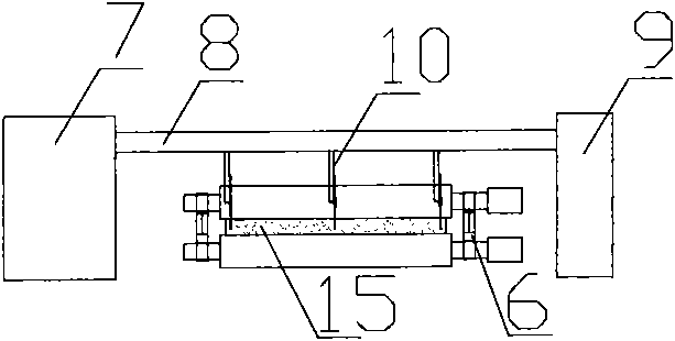
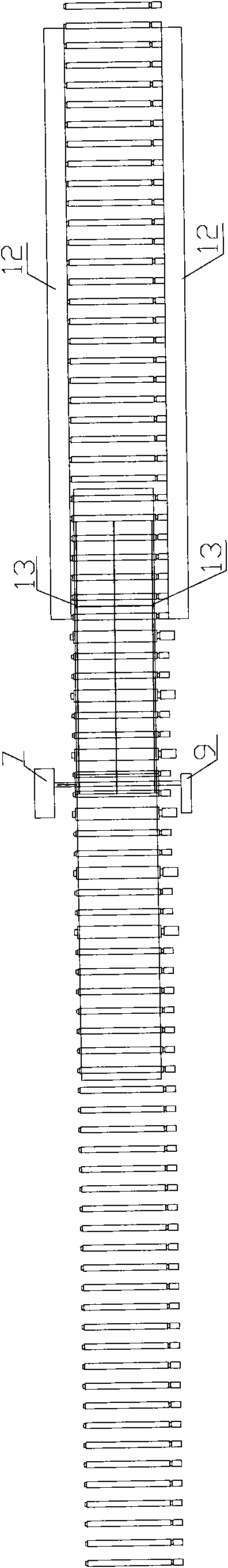
[0028] refer to figure 1 , figure 2 and image 3 Shown in the figure are respectively the structural schematic diagram, left side view and top view of the continuous reversible precision sawing machine of the present invention. As can be seen from the above drawings, the continuous reversible precision sawing machine of the present invention mainly includes the following components:

[0029] The sawing host, as the main equipment of the whole sawing machine, is used to saw the incoming material (stack) 15 of different specifications into the required size state. The sawing host adopts the form of a gantry saw, including a gantry frame and a circular saw 10 arranged on the gantry frame. Specifically, the gantry frame includes a main frame 7 , an auxiliary frame 9 , and a beam guide rail 8 connecting the main frame 7 and the auxiliary fram...


PUM


Abstract

The invention relates to a continuous reversible precision sawing machine, comprising a saw cutting main machine, a roller way and a pressing roller group, wherein the saw cutting main machine comprises a gantry frame and a circular disc saw, and the circular disc saw is arranged on a cross beam guide rail of the gantry frame; the roller way is laid under the gantry frame and comprises a receiving roller way, a working roller way and a finished product discharging roller way, and the working roller way can rotate forward and reversely; and the pressing roller group is arranged on the working roller way and is used for pressing a plate on the working roller way in the process of saw cutting. The sawing machine adopts a pressing mode with the pressing roller group, respectively applies dynamic pressing to the plate in the whole process of saw cutting, can realize multi-pass and multi-mode high-accuracy saw cutting and improve metal yield when in saw cutting.

Description

technical field [0001] The invention relates to a sawing device, in particular to a continuous reversible precision sawing machine. Background technique [0002] In recent years, major sawing equipment manufacturers and medium and thick plate manufacturers at home and abroad have made various active explorations and attempts for precision sawing of medium and thick plates. Among them, the products designed and developed by some foreign companies are relatively impressive, but there are also many shortcomings and problems. Most precision sawing machines have greatly sacrificed sawing efficiency and metal yield when ensuring high-precision sawing. [0003] The reason lies mainly in the impact of the clamping and fixing method of the plate on the working mode and working efficiency of the sawing machine during the sawing process. The precision sawing equipment designed and developed by well-known sawing equipment companies at home and abroad, which are widely used at present,...

Claims


Application Information

Patent Timeline
Patent Type & Authority Applications(China)
IPC IPC(8): B23D47/00B23D47/04B23D59/00
Inventor 孙全民闫文彪李强
Owner BERIS ENG & RES CORP
Why Eureka
Try Eureka