Flame cutting system with insulation device for flame cutting zone of billet

A technology of flame cutting and heat preservation device, used in gas flame welding equipment, welding equipment, metal processing equipment and other directions, can solve the problems of prolonged cutting time, complex mechanism, low billet drawing speed, etc., to ensure performance and strength, solve the problem of shaft The effect of end sealing and preventing damage to the roller table

Inactive Publication Date: 2010-10-20
何学才
View PDF1 Cites 5 Cited by
  • Summary
  • Abstract
  • Description
  • Claims
  • Application Information

AI Technical Summary

Problems solved by technology

Hot delivery and hot charging of steel billets in iron and steel plants are very common and have achieved good energy-saving effects. However, at present, hot billets are generally transported in an open manner. The billets are thick and wide, with low casting speed, long cutting time, large heat dissipation, and metal oxidation. loss, the edge of the billet cools quickly, and cracks are easy to occur for some steel types, which affects product quality. Some factories at home and abroad also take heating measures for the edge of the billet. Due to technical difficulties (the most important of which is how to take insulation measures in the cutting area), it has not fully realized full insulation, hot loading and hot delivery.
[0003] Billet flame cutting is carried out while the billet is being cut while

Method used


Image

  • Flame cutting system with insulation device for flame cutting zone of billet
  • Flame cutting system with insulation device for flame cutting zone of billet
  • Flame cutting system with insulation device for flame cutting zone of billet

Examples


Embodiment

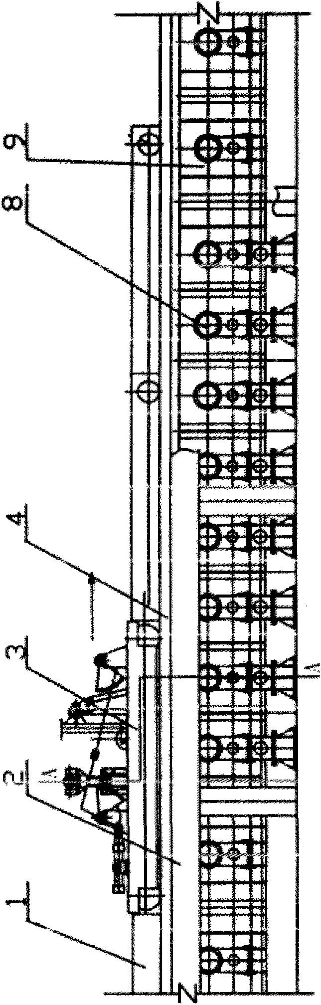
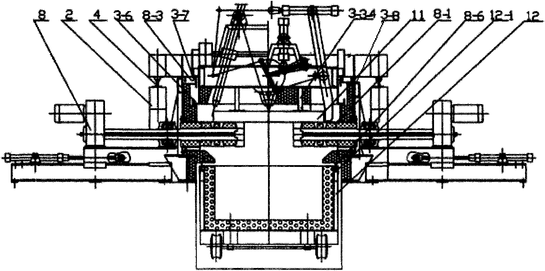
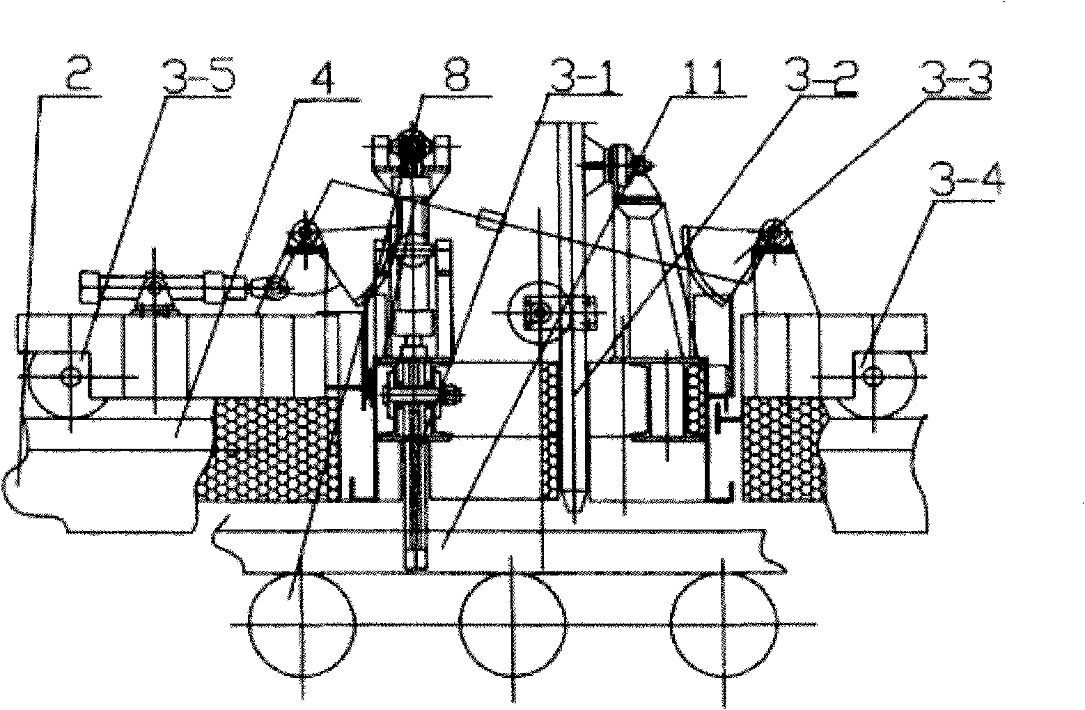
[0035] Such as figure 1 As shown, a flame cutting system for a steel billet flame cutting area with a thermal insulation device provided by the present invention includes track beams 2 located on both sides, and a heavy rail 4 is respectively arranged on the top of each track beam 2, and the flame cutting The car 3 moves back and forth on the heavy rail 4, and at least one mobile heat preservation cover 1 is connected to the front end and the rear end of the flame cutting car 3 respectively, and the mobile heat preservation covers 1 are connected to each other and are on the heavy rail 4 together with the flame cutting car 3 Move back and forth, between the two track beams 2, there is a row of water internally cooled conveying billet roller table 9 and billet cantilever roller table 8 with heat preservation device, the billet 11 located under the flame cutting vehicle 3 is on the billet cantilever roller table 8 front and rear move.

[0036] When the billet 11 detects the len...


PUM


Abstract

The invention provides a flame cutting system with an insulation device for a flame cutting zone of billets, which comprises track beams arranged on both sides. The top parts of the track beams are respectively provided with a heavy track, a flame cutting trolley slides back and forth on the heavy tracks, the front end and the rear end of the flame cutting trolley are respectively connected with at least one mobile insulation cover, the mobile insulation covers are connected with each other and slide back and forth on the heavy tracks along with the flame cutting trolley, a row of internal water cooling billet-conveying rollers with an insulation device are arranged between the two track beams, billet cantilever rollers penetrate through the internal water cooling billet-conveying rollers, and billets arranged below the flame cutting trolley slide back and forth on the billet cantilever rollers. The invention has the advantages of minimizing the heat dissipation of the billets, preventing the air leakage of the joint surface, effectively solving the problem of sealing the shaft end, efficiently preventing heat dissipation, ensuring the performance and strength of the roller rings, and reducing the consumption of cooling water.

Description

technical field [0001] The invention provides a billet cutting area flame cutting system with a thermal insulation device, which is used in a hot billet hot feeding and charging device in a steel plant, and belongs to the technical field of the billet flame cutting area flame cutting device. Background technique [0002] Iron and steel enterprises are large energy consumers, and there is still great energy-saving potential. High-quality, energy-saving, consumption reduction, and benefit are the goals that enterprises always pursue. Energy-saving and emission-reduction are twin brothers. Carbon will now be a political issue, and it has now been elevated to a major issue of human existence. Hot delivery and hot charging of steel billets in iron and steel plants are very common and have achieved good energy-saving effects. However, at present, hot billets are generally transported in an open manner. The billets are thick and wide, with low casting speed, long cutting time, larg...

Claims


Application Information

Patent Timeline
IPC IPC(8): B23K7/00B23K7/10
Inventor 何学才
Owner 何学才
Why Eureka
Try Eureka