Vibration damper and downhole drill comprising the same

A vibration damping device and drill pipe technology, which is applied in the direction of the driving device, drill pipe, and drill pipe for drilling in the borehole, can solve the problems of limited elastic deformation, limited vibration damping effect of the vibration damping device, and strong impact, etc., to achieve The effect of reducing impact vibration and optimizing vibration damping effect

Inactive Publication Date: 2010-10-20
BEIJING SANY HEAVY MASCH CO LTD
View PDF10 Cites 19 Cited by
  • Summary
  • Abstract
  • Description
  • Claims
  • Application Information

AI Technical Summary

Problems solved by technology

[0008] Although the above prior art can buffer the impact vibration transmitted from the drill pipe to the power head to a certain extent, the actual damping effect is greatly limited
Since the impact frequency of the impactor of the down-the-hole drilling rig is in the range of 10-50Hz, the impact vibration transmitted upwards through the drill pipe changes greatly, and the impact is relatively strong; it is difficult to ensure that the rubber or other elastic mechanisms produce an appropriate amount of deformation. The damping effect of the damping device is greatly limited; in addition, the amount of elastic deformation of the rubber or other elastic mechanisms is very limited after being stressed, which also limits the buffer distance of the damping device, which greatly limits the damping effect
[0009] At the same time, not only the longitudinal force is transmitted between the drill pipe and the power head, but also the rotational driving force is transmitted; this makes the force condition of the vibration damping device more complicated, and the complex force condition is very easy to cause the rubber or other elastic mechanisms to shear Fatigue failure under force, compression and tension, which reduces the reliability of the vibration damping device

Method used


Image

  • Vibration damper and downhole drill comprising the same
  • Vibration damper and downhole drill comprising the same
  • Vibration damper and downhole drill comprising the same

Examples


Embodiment Construction

[0035] The present invention will be described in detail below in conjunction with the accompanying drawings. The description in this part is only exemplary and explanatory, and should not have any limiting effect on the protection scope of the present invention.

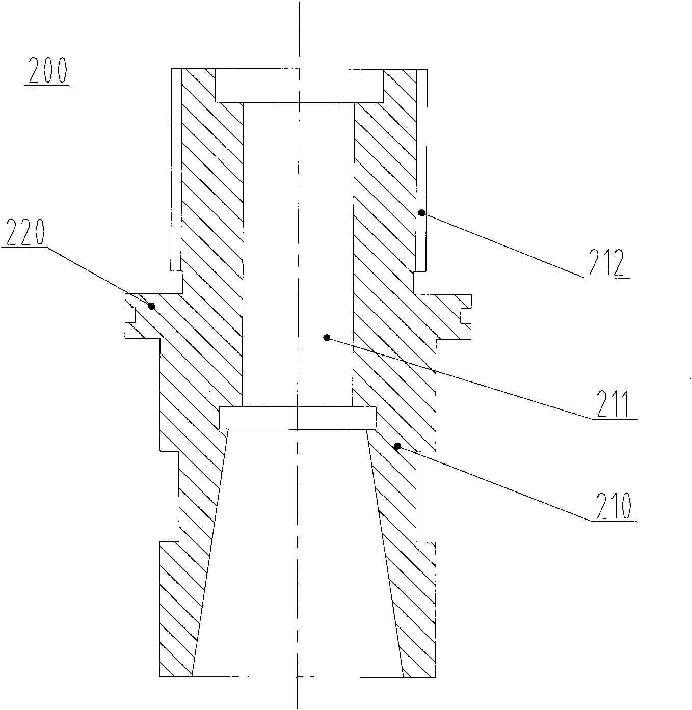
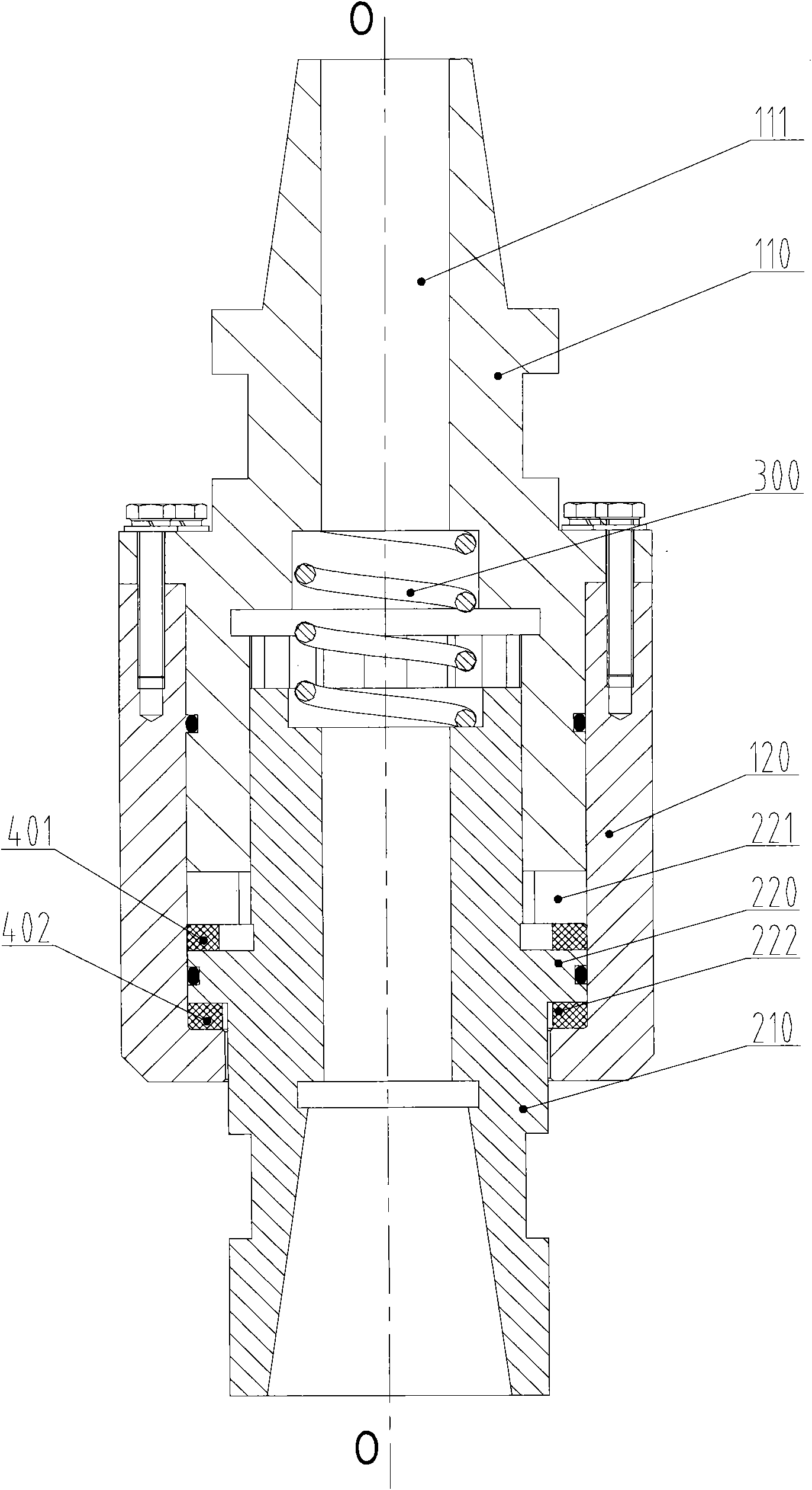
[0036] The vibration damping device provided in this embodiment includes a first joint 100 and a second joint 200 . The structures of the first joint 100 and the second joint 200 are described respectively below.

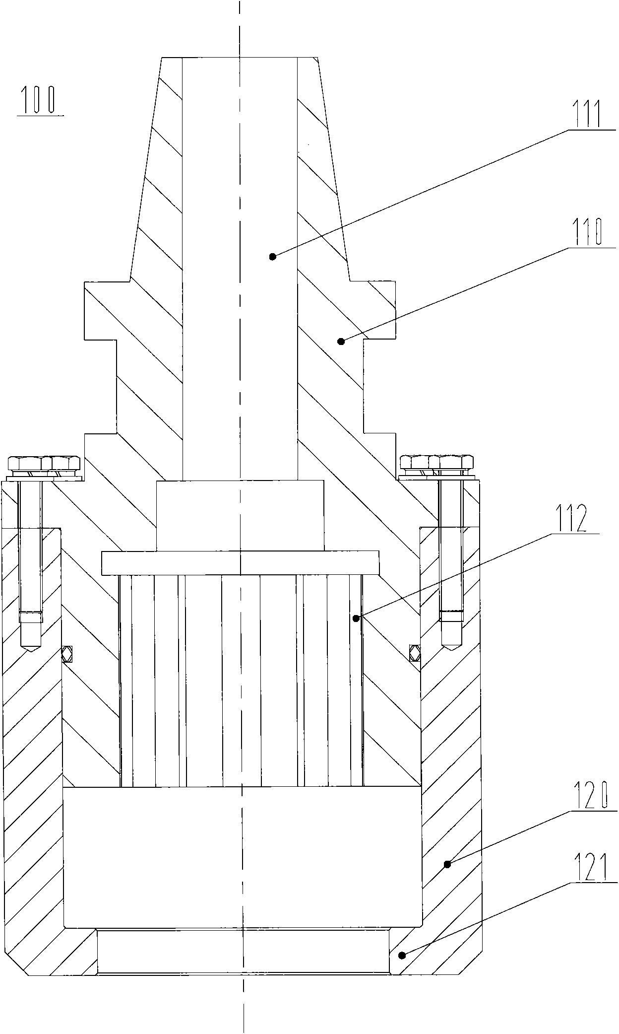
[0037] Please refer to figure 1, which is a schematic structural diagram of the first joint in the vibration damping device provided by the embodiment of the present invention. The first joint 100 includes a first joint body 110 and a sleeve 120 , and the first joint body 110 and the sleeve 120 are fixed together by fasteners; the first joint body 110 has a central through hole 111 inside. An inner spline groove 112 is provided near the lower end of the first connector body 110 , and the centerline of t...


PUM


Abstract

The invention discloses a vibration damper and a downhole drill comprising the same. The vibration damper comprises a first joint and a second joint, and the first joint and the second joint are respectively provided with a central through hole. The vibration damper is characterized in that the second joint comprises a piston body; the piston body and the first joint can be longitudinally and glidingly matched; a first cavity is formed between one end of the piston body, which faces the first joint, and the first cavity is communicated with the central through hole of the first joint. When the vibration damper is utilized, the second joint compresses high-pressure gas in the first cavity to enable the volume of the first cavity to generate changes, and the high-pressure gas in the first cavity absorbs vibration energy to achieve the goals of buffering and vibration damping; due to the fact that the pressure change of the high-pressure gas is smaller, the change of an acting force transferred to the first joint through the first cavity is smaller, and further, the peak value of an impact force transferred to the first joint by the second joint can be better limited, and the impact vibration is reduced so that the vibration damper has more superior vibration damping effect.

Description

technical field [0001] The invention relates to a vibration reduction technology, in particular to a vibration reduction device, and also to a down-the-hole drilling machine comprising the vibration reduction device. Background technique [0002] Down-the-hole drilling rigs are widely used in ore mining, engineering construction and other fields. The down-the-hole drilling rig has a rotary drive mechanism and an impact mechanism, and uses the impactor and drill bit that dive into the bottom of the hole to impact and break the predetermined formation to form a predetermined hole. [0003] Generally speaking, the working device of a down-the-hole drilling rig mainly includes a drill frame, a power head, a drill pipe, a hammer and a drill bit. The upper end of the drill pipe is connected with the power head, the lower end is connected with the hammer, and the drill bit is installed at the lower end of the hammer. The power head is installed on the drill frame and is used to d...

Claims


Application Information

Patent Timeline
Patent Type & Authority Applications(China)
IPC IPC(8): E21B17/07E21B4/00
Inventor 冯祥文赵长春
Owner BEIJING SANY HEAVY MASCH CO LTD
Why Eureka
Try Eureka