Sliding door type vertical-axis wind driven generator

A technology of wind power generators and vertical shafts, which is applied to wind power generators, wind power motor combinations, wind power generators at right angles to the wind direction, etc., which can solve problems such as reducing power generation efficiency, and achieve convenience in repair and maintenance, high work efficiency, and widening The effect of material range

Inactive Publication Date: 2010-10-20
阎波
View PDF4 Cites 3 Cited by
  • Summary
  • Abstract
  • Description
  • Claims
  • Application Information

AI Technical Summary

Problems solved by technology

[0004] In order to solve the above-mentioned problem that the power generation efficiency of the vertical axis wind t...

Method used


Image

  • Sliding door type vertical-axis wind driven generator
  • Sliding door type vertical-axis wind driven generator
  • Sliding door type vertical-axis wind driven generator

Examples


Embodiment Construction

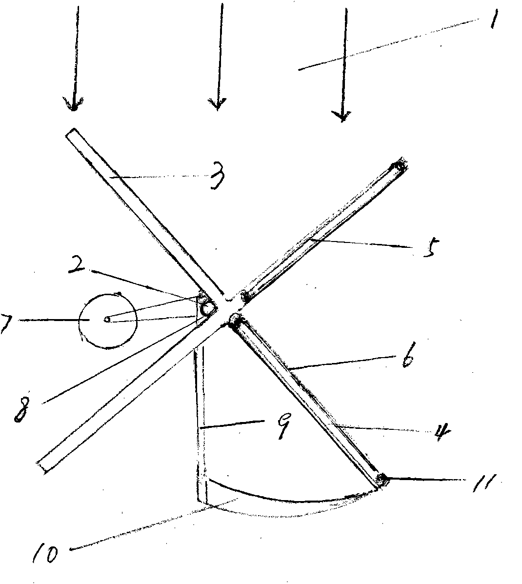
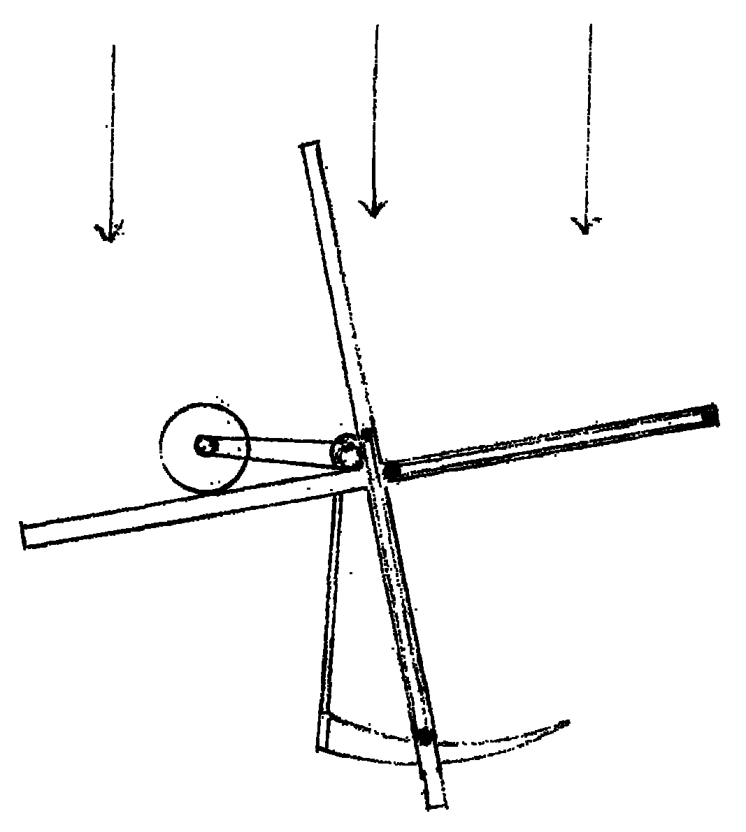
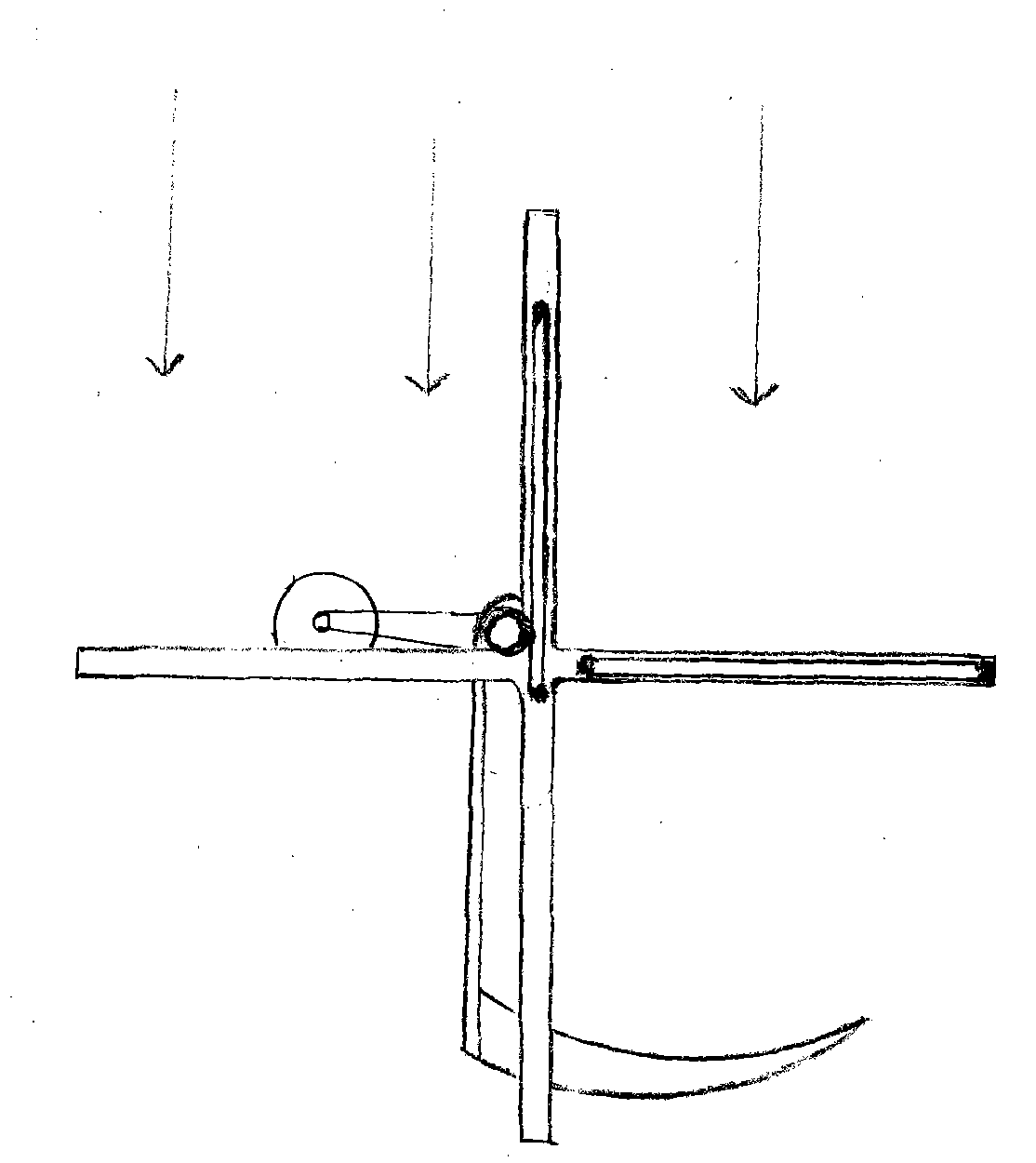
[0057] The electric embodiment in the present invention is described as follows in conjunction with accompanying drawing:

[0058] 1. Use a round steel with a length of 6M and a diameter of 8CM to make a vertical shaft, and weld 8 channel steels with a length of 5M and a width of 8CM to form two cross-shaped groove rails. Install buffer springs inside each end of the groove rails and externally Set the elastic lock for stabilizing the blades;

[0059] 2. The cross-shaped groove rails are separated by 5M and stand upright in an X shape, and the vertical shaft is placed above the intersection of the two cross-shaped groove rails and welded firmly;

[0060] 3. Stand upright the assembled vertical shaft with cross groove rail;

[0061] 4. According to the gap between the upper and lower rails, two sliding door fan blades are made with the corner frame and glass cloth of appropriate specifications. The lower end of the fan blades is equipped with rolling wheels, horizontal top whe...


PUM


Abstract

The invention discloses a sliding door type vertical-axis wind driven generator. A cruciform plane crossing groove rail which can drive the vertical shaft or a hub to rotate is installed on a vertical shaft of a fan. A fan blade with a rolling wheel is installed on the groove rail; and by using an electrical machine or a top rail which can support and move the fan blade in the rotation of the fan, the fan blade after obtaining wind energy is directly supported back to an upper tuyere of the fan from a lower tuyere of the fan like a sliding door and the wind energy is immediately intercepted. In the invention, a rotary type back movement of the original fan blade is replaced by a straight-line back movement, thereby greatly reducing a back-moving area and a back-moving distance of the fan blade, lightening wind loss of the back movement and improving work efficiency of the fan, so the invention has a certain development value.

Description

technical field [0001] The invention relates to a vertical axis wind power generator. It can be realized in two ways: the first is the electric type, which is composed of the vertical shaft of the fan, cross-shaped groove rails, sliding door fan blades, power motors, generators and top blade rails with wind rudders; the second type It is an automatic type, which is composed of a fixed column, a connecting frame, a rectangular frame, a wind rudder plate, a directional ground wheel, a fixed top blade rail, a vertical shaft of the fan, a cross groove rail, a sliding door type fan blade, and a generator. Background technique [0002] At present, the depletion of non-renewable energy and global warming have posed a serious threat to human existence. For this reason, people are constantly developing renewable or light-pollution new energy sources. Because wind resources are both renewable and non-polluting, they have Therefore, the use of wind resources to generate electricity ha...

Claims


Application Information

Patent Timeline
IPC IPC(8): F03D9/00F03D3/00F03D3/06
CPCY02E10/74
Inventor 阎波
Owner 阎波
Why Eureka
Try Eureka