
Illumination device

A lighting device and heat dissipation base technology, applied in lighting devices, lighting device parts, lighting device cooling/heating devices, etc. Device reliability, etc.

Inactive Publication Date: 2010-10-20
FU ZHUN PRECISION IND SHENZHEN +1
View PDF5 Cites 5 Cited by
  • Summary
  • Abstract
  • Description
  • Claims
  • Application Information

AI Technical Summary

Problems solved by technology

[0004] The application of high-power and high-brightness LEDs in the new light source of lighting must cooperate with a high-efficiency heat dissipation mechanism to minimize the junction temperature of the LEDs in order to take advantage of the above-mentioned advantages. Otherwise, the luminous brightness and service life of the lighting device will be greatly reduced, affecting all And will make the energy-saving effect of the lighting device not obvious, and directly impact the reliability of the lighting device, cause serious light decay and even make the lighting device invalid
[0005] Existing semiconductor lighting devices try to achieve the heat released when the light source emits light by increasing the heat dissipation area. However, in the limited space allowed by the lighting device, how to quickly and evenly dissipate the heat of the high heat flux of the light source Transfer to the heat dissipation area, and how to quickly remove the heat transferred to the heat dissipation area, become an important pointer to reduce the junction temperature of the LED light source; therefore, provide a long-term stable, no external power, and can Heat removal devices that produce different degrees of boiling as the temperature of the heating component changes, quickly dissipating the heat of the heating component has become a challenge for related industries

Method used


Image

  • Illumination device
  • Illumination device
  • Illumination device

Examples


Embodiment Construction

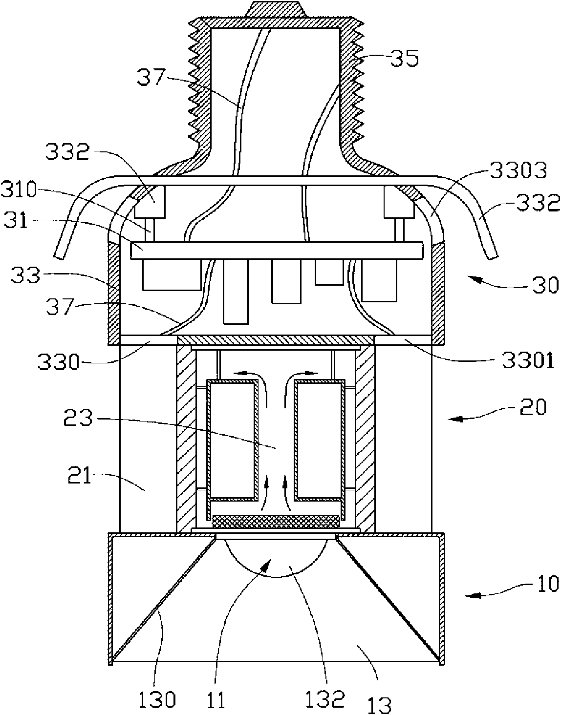
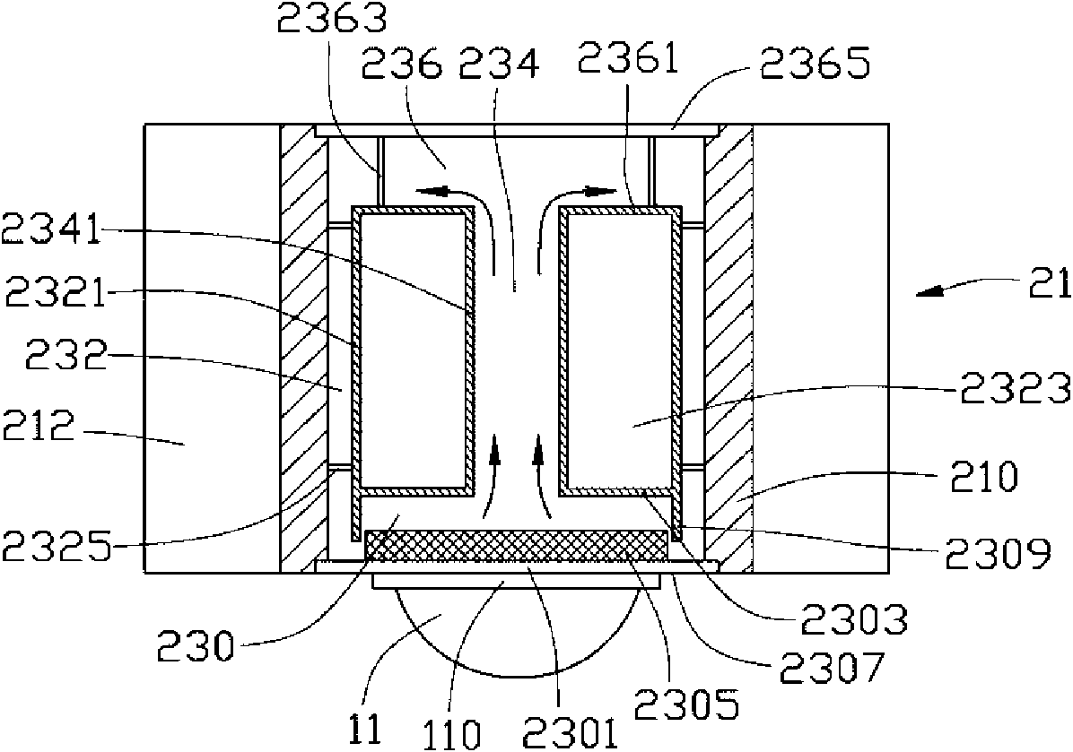
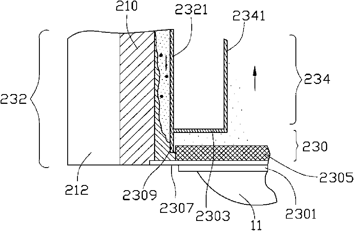
[0022] figure 1 is a schematic cross-sectional view of the assembly of the first embodiment of the lighting device of the present invention, figure 2 yes figure 1 Schematic diagram of the assembly cross-section of the light engine, image 3 yes figure 1 Schematic diagram of the phase change of the working fluid inside the light engine; the lighting device mainly includes an optical part 10 , a heat dissipation part 20 and an electrical part 30 .

[0023] The optical part 10 is arranged under the heat dissipation part 20, and includes at least one light source 11 composed of semiconductor light emitting components (for example, LED) and at least one light exit channel 13. The light source 11 is closely connected to the outer surface of the lower cover 2301 of the heat dissipation part 20 Thermal contact, and a layer of thermal interface material (TIM) can be applied in between, and then several screws (not shown) that have been fitted with electrical insulating gaskets a...


PUM


Abstract

The invention discloses an illumination device, which comprises an optical part, an electric part, and a radiating part which is arranged between the optical part and the electric part. The radiating part comprises a radiator and a loop device, wherein the radiator comprises a hollow radiating base and a plurality of fins which are thermally connected with an outer surface of the radiating base; and the loop device is arranged inside the radiating base, so that the radiating base forms an outer wall of the loop device. The loop device also comprises a cylindrical part, a lower cover, and an upper cover, wherein the cylindrical part is arranged inside the radiating base and is provided with at least one axial through hole; the lower cover is made of a material with good thermal conductivity, and the outer surface of the lower cover is thermally connected with a light source; the lower cover and the upper cover seal two ends of the radiating base respectively, so that an evaporating part is formed between the lower end of the cylindrical part and the lower cover; a condensation part is formed between an outer surface of the cylindrical part and an inner surface of the radiating base; and the through hole of the cylindrical part forms at least one steam channel which is communicated with the evaporating part and the condensation part. By means of the phase change of working fluidin the loop device, the released heat of the light source is continuously removed at high radiating efficiency when the light source illuminates.

Description

technical field [0001] The invention relates to a lighting device, in particular to a semiconductor lighting device with high heat dissipation efficiency. Background technique [0002] People's long-term over-reliance on fossil fuels not only hinders economic development due to energy shortages and high oil prices, but also increases the concentration of global carbon dioxide and harmful gas emissions, leading to climate abnormalities caused by global warming, ecological environment damage, and The harm to human existence is becoming more and more obvious. In order to sustainably manage the earth's ecological environment on which human beings depend, it is necessary to solve the energy crisis and environmental pollution problems at the same time. The development of new energy and renewable energy is the most important strategy to promote energy conservation and efficient use of energy , while traditional lighting consumes a considerable amount of energy, the development of l...

Claims


Application Information

Patent Timeline
Patent Type & Authority Applications(China)
IPC IPC(8): F21S2/00F21V23/00F21V29/00H01L23/367H01L23/427F21Y101/02
CPCF21V29/02H01L2924/0002F21V29/006F21V29/004F21K9/00F21V29/246F21V29/2231F21V29/2293F21V29/027F21V29/677F21V29/773F21V29/83F21V29/89F21V29/51F21V29/74F21V29/67H01L2924/00
Inventor 刘泰健
Owner FU ZHUN PRECISION IND SHENZHEN
Learn More