Expansion sleeve type cast-aluminum dummy shaft

A technology of expanding sleeves and dummy shafts, which is applied in the field of dummy shafts, can solve the problems of scrapped cast aluminum rotors, difficulties in withdrawing shafts, and affecting motor vibration, and achieve the effects of saving lamination time, reducing metal processing procedures, and improving uniformity

Inactive Publication Date: 2010-10-20
WUXI ZHONGDA MOTORS
View PDF0 Cites 11 Cited by
  • Summary
  • Abstract
  • Description
  • Claims
  • Application Information

AI Technical Summary

Problems solved by technology

This is bound to affect the vibration of the motor
If the method of improving the accuracy of the cast aluminum dummy shaft and the tolerance is close to the true shaft, it will bring two problems: one is that it is difficult to laminate and reduce production efficiency; The guide bar breaks, causing the cast aluminum rotor to be scrapped
If the cast aluminum rotor shaft hole is used to match the motor shaft, there are also the following problems in the actual operation process: (1) After the cast aluminum rotor shaft hole is processed, there are chips between the punches, which are not easy to clean. Segmented cast aluminum rotors with radial air passages, if the iron filings entering the air passages are not cleaned, there will be hidden dangers to the safe operation of the motor; (2) The behavior tolerance of the rotor iron core shaft hole after gold processing is not easy to control
[0003] The original dummy shaft is punched with a small part of the dummy shaft when it is stacked. Clearance fit between shafts, after the cast aluminum rotor is cast, the inner and outer diameters are relatively uneven

Method used


Image

  • Expansion sleeve type cast-aluminum dummy shaft
  • Expansion sleeve type cast-aluminum dummy shaft

Examples


Embodiment Construction

[0008] The present invention will be further described below in conjunction with specific drawings and embodiments.

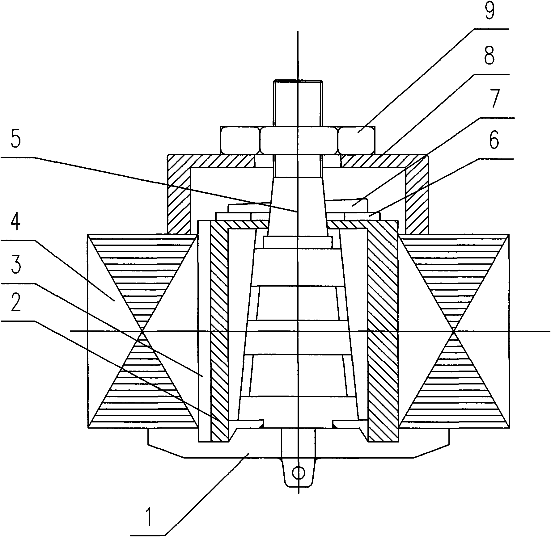
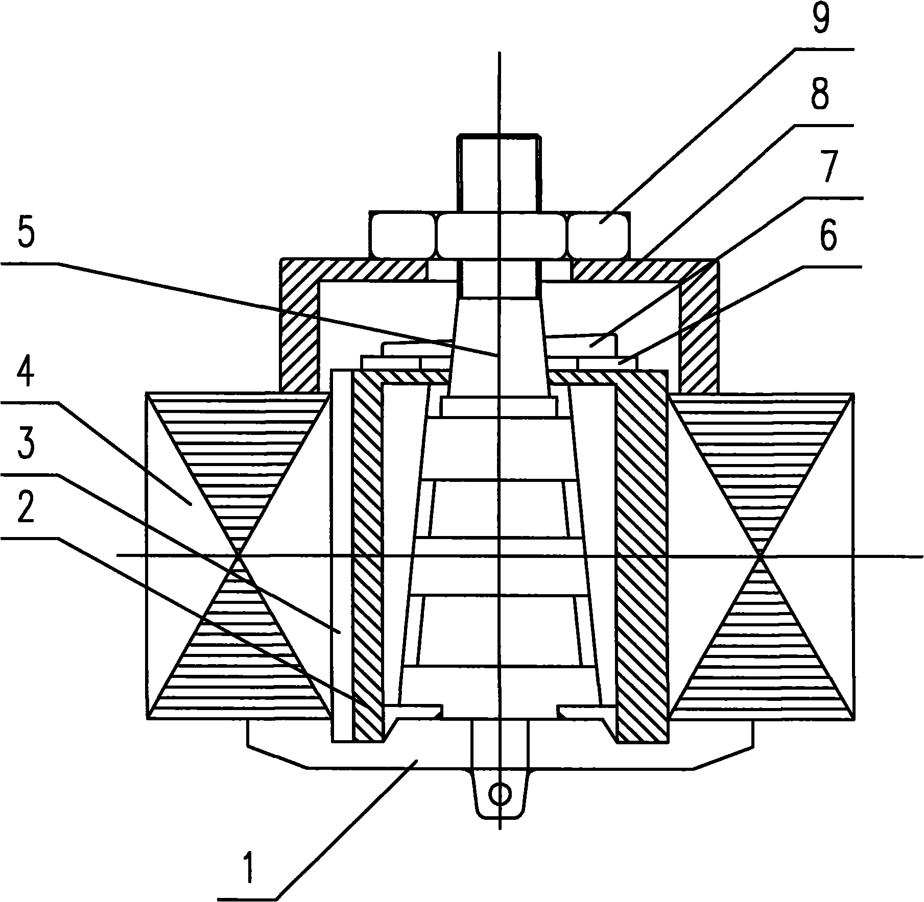
[0009] As shown in the figure: the present invention is mainly composed of shaft seat 1, expansion sleeve 2, positioning key 3, rotor core 4, mandrel 5, backing plate 6, wedge plate 7, pressure plate 8 and fastening nut 9, etc.

[0010] The expansion sleeve type cast aluminum dummy shaft includes a mandrel 5 arranged on the shaft seat 1, and an expansion sleeve 2 is set on the outer surface of the mandrel 5. The outer surface of the expansion sleeve 2 is provided with an external keyway along its axial direction, and the keyway is inserted The positioning key 3 is connected, and the rotor core 4 is set outside the expansion sleeve 2. The side wall of the inner hole of the rotor core 4 is installed with an inner keyway along its axial direction, and the outer end of the positioning key 3 is inserted into the inner keyway. , the mandrel 5 is sleeved with a pressu...


PUM


Abstract

The invention relates to an expansion sleeve type cast-aluminum dummy shaft. A core shaft is arranged on a shaft base; an expansion sleeve is sleeved outside the core shaft; an outer key groove is formed on an outer surface of the expansion sleeve along the axial direction; a positioning key is inserted in the key groove; and a rotor core is sleeved outside the expansion sleeve. The side wall of a rotor core mounting inner hole is provided with an inner key groove along the axial direction; an outer end of the positioning key is inserted in the inner key groove; a pressing plate which is used for pressing the rotor core is sleeved on the core shaft; and a fastening nut which makes the pressing plate tightly support the rotor core is screwed on the core shaft. The expansion sleeve type cast-aluminum dummy shaft is characterized in that: a section of core shaft which is sleeved with the expansion sleeve is a cone; a base plate which is pressed against an end face of the expansion sleeve is sleeved on the core shaft; and a wedged plate is arranged on the core shaft on the upper part of the base plate. The expansion sleeve type cast-aluminum dummy shaft can completely expand the inner diameter of the core, improve the uniformity of cast-aluminum rotor shaft hole, and reduce metal working procedures. Meanwhile, after aluminum is cast on the rotor, because the core shaft is matched with the conical surface of a trivalve sleeve, the shaft withdrawal is convenient, labor-saving, and time-saving.

Description

technical field [0001] The invention relates to a dummy shaft used in punching and lamination of the rotor in the aluminum casting process of the rotor, in particular to an expansion sleeve type dummy shaft of cast aluminum. Background technique [0002] The vibration and noise of the three-phase asynchronous motor are the hard quality indicators in the competition of the motor in the same industry. In order to solve the vibration problem, it is necessary to take measures to control it from all aspects of motor manufacturing. The rotor cast aluminum shaft in the motor industry generally adopts a solid shaft, which is only slightly different from the true shaft in terms of tolerance. Due to the clearance between the punched sheet and the dummy shaft during lamination, after the cast aluminum rotor is cast, the inner and outer diameters are relatively uneven. . This is bound to affect the vibration of the motor. If the method of improving the accuracy of the cast aluminum d...

Claims


Application Information

Patent Timeline
Patent Type & Authority Applications(China)
IPC IPC(8): H02K15/02
Inventor 刘小东
Owner WUXI ZHONGDA MOTORS
Why Eureka
Try Eureka