Magnetic valve

A valve seat and double valve technology, applied in the field of magnetic valves, can solve the problems of miniaturization difficulties, reduction of structural space of fluid joints and electrical joints, etc., and achieve the effect of compact structure

Inactive Publication Date: 2010-10-20
BURKERT WERKE
View PDF6 Cites 2 Cited by
  • Summary
  • Abstract
  • Description
  • Claims
  • Application Information

AI Technical Summary

Problems solved by technology

At the same time, the manufacturing tolerances of the individual components can only be reduced at high expense
Also difficult for mi...

Method used


Image

  • Magnetic valve
  • Magnetic valve
  • Magnetic valve

Examples


Embodiment Construction

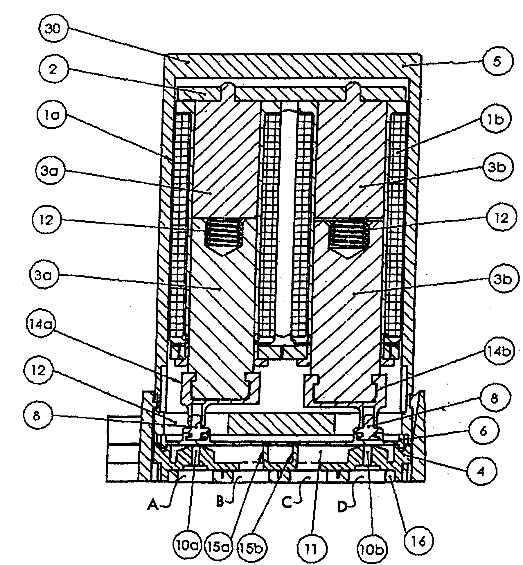
[0025] In the compound valve according to the invention, not only the fluid and electrical connections, but also the other valve internal parts of both valves are assembled in one housing. This results in a very compact construction of the valve and an additional cost savings due to the common components—valve housing, diaphragm, magnetic circuit, electrical connections, coil casing—that are shared by both valves. The dual valve is compatible with known three-way valves not only in terms of external dimensions but also in terms of fluid connections and electrical connections, so that the two valve types can be easily combined with one another in the system. In another embodiment of the dual valve, the fluid components of the two valves are connected, although the two drives of the valves can be connected independently of one another. This results in a three-way valve with three possible switching positions: two valve seats closed; one valve seat closed and one valve seat open;...


PUM


Abstract

The invention relates to a double valve, having two inductors (1a, 1b) which can be controlled independently of each other and which each have a core (3a, 3b), having a common valve housing (5, 7) in which the inductors (3a, 3b) are arranged, having a flange housing (4) which is attached to the valve housing (5, 7) and in which two valve seats (10a, 10b) are arranged, and having a membrane (6) assigned to the two valve seats (10a, 10b). Each inductor (3a, 3b) is assigned to a valve seat (10a, 10b).

Description

technical field [0001] The invention relates to an (electro)magnetic valve with which a fluid connection can be made. Background technique [0002] Such solenoid valves are known in various designs. An example is given in DE 201 00471 U1. It has an adjusting drive with two coils that actuate the switch-on rocker. The switch-on rocker acts on a diaphragm, which in turn can cooperate with the two valve seats. The diaphragm simultaneously forms a separation between the actuating drive and the fluid side of the valve. [0003] It is often attempted to make such valves more compact. However, the more compact the valve is, the tighter the manufacturing tolerances are, since the actuating force achievable by the valve's actuating drive (preferably a solenoid coil) decreases significantly with a reduced overall volume. At the same time, the manufacturing tolerances of the individual components can only be reduced at great expense. Furthermore, what makes miniaturization diffic...

Claims


Application Information

Patent Timeline
IPC IPC(8): F16K31/06
CPCF16K27/003F16K31/0679F16K7/14F16K11/24F16K31/0675F16K31/082Y10T137/5109Y10T137/87096
Inventor C·黑廷格
Owner BURKERT WERKE
Why Eureka
Try Eureka