Material loading frame of welding machine

A material rack and welding machine technology, applied in welding equipment, auxiliary welding equipment, welding/cutting auxiliary equipment, etc., can solve the problems of non-continuous production, low production efficiency, time-consuming, etc., to avoid shaking, simple and practical structure Effect

Inactive Publication Date: 2010-10-27
NINGBO XINZHOU RESISTANCE WELDER
View PDF4 Cites 10 Cited by
  • Summary
  • Abstract
  • Description
  • Claims
  • Application Information

AI Technical Summary

Problems solved by technology

But the feeding frame of welding machine in the prior art also has following deficiency: for saving space, the length of rail frame is limited, can only be provided with a mold frame on rail frame, after the weldment welding on the mold frame is finished, will weld Good weldments are removed from the loading rack and returned to the front end of the bracket to stop and wait for the next batch of weldments to be installed. The production process is interrupted and continuous production cannot be performed. This will result in more time-consuming process and lower production efficiency. Low

Method used


Image

  • Material loading frame of welding machine
  • Material loading frame of welding machine
  • Material loading frame of welding machine

Examples


Embodiment Construction

[0027] The present invention will be further described below in conjunction with the accompanying drawings and specific embodiments.

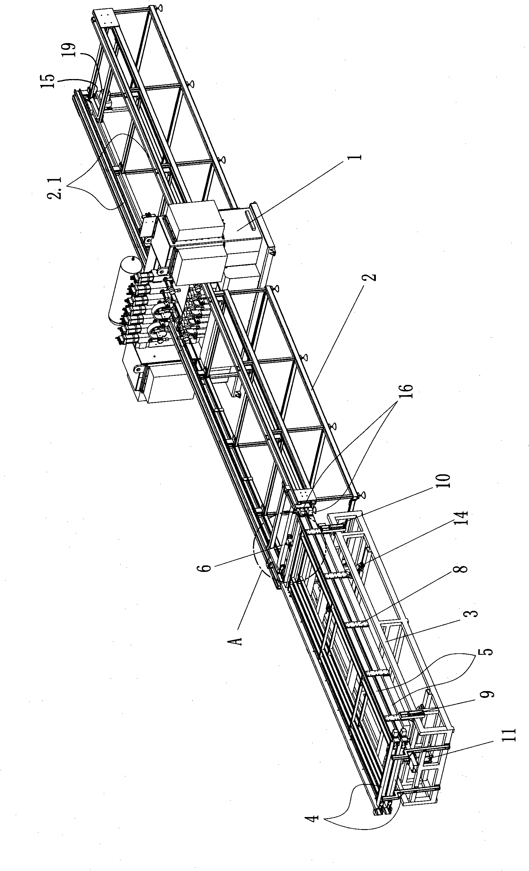
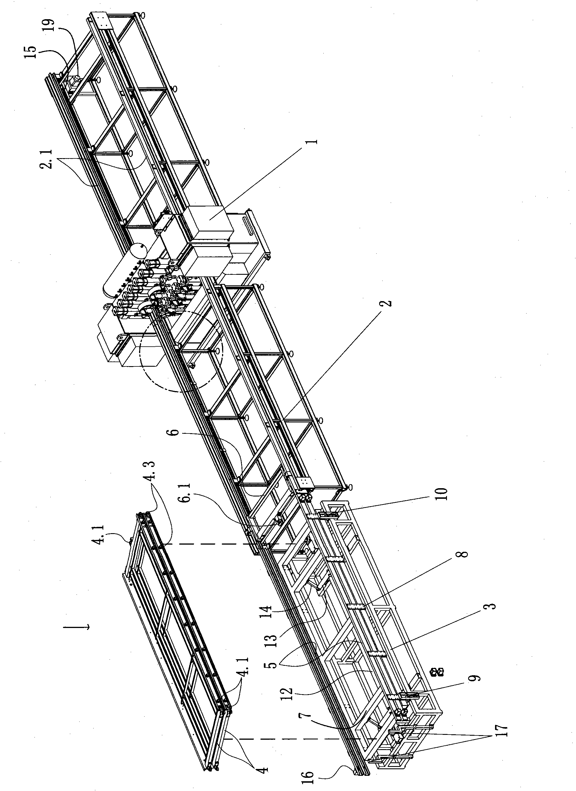
[0028] Such as figure 1 , figure 2 As shown, the loading frame of the welding machine of the present invention includes a mold frame 4 and a rail frame 2 used in conjunction with the welding machine 1, and the rail frame is provided with a driving device for dragging the mold frame 4.

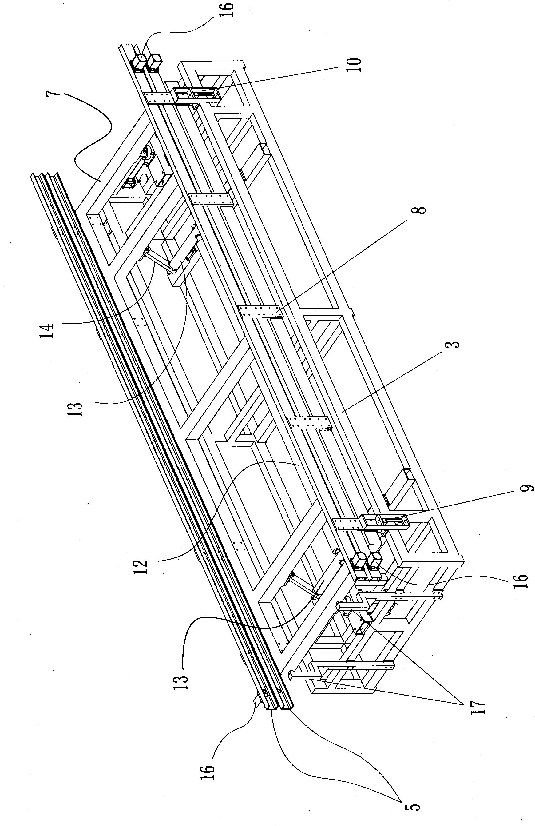
[0029] It also includes a support frame 3 and a two-layer feeding guide rail 5. The support frame 3 is provided with a lifting device, and the two-layer feeding guide rail 5 is connected with the lifting device and can be alternately connected with the guide rail 2.1 on the guide rail frame 2. Docking; described mold frame 4 has two layers, and described two-layer mold frame 4 is slidingly fitted on the two-layer feeding guide rail 5 of support frame 3 respectively (that is, each layer of feeding guide rail 5 is provided with a layer of mold frame 4); the gui...


PUM


Abstract

The invention relates to a material loading frame of a welding machine, comprising mould frames and a guide rail frame matched with the welding machine. A driving device is arranged on the guide rail frame. The material loading frame also comprises a supporting frame and two layers of material loading guide rails, wherein the supporting frame is provided with an elevation device, and the two layers of material loading guide rails are connected with the elevation device and can form butt joint with the guide rails on the guide rail frame alternatively under the drive of the elevation device; the mould frames have two layers, and the two layers of mould frames are respectively matched on the two layers of material loading guide rails of the supporting frame in a sliding mode; a drawing plate for drawing the mould frames is also arranged on the guide rails of the guide rail frame; the mould frames are connected or disconnected with the drawing plate; and the drawing plate is connected with the driving device. The two layers of material loading guide rails which can form butt joint with the guide rails on the guide rail frame alternatively can realize the alternative use of the two layers of mould frames, continuous production can be performed, and therefore, the production efficiency of the welding machine is greatly improved.

Description

Technical field: [0001] The invention relates to a welding device, in particular to a material loading rack of a welding machine. Background technique: [0002] In the prior art, for the convenience of operation, welding machines are used in conjunction with feeding racks. Usually, the loading frame includes a guide rail frame and a mold frame. The mold frame can move back and forth along the guide rail on the rail frame. Afterwards, the welding piece frame is moved from the front end to the rear end of the guide rail frame by the driving device and the welding piece is transported to the working position, and the welding piece is welded by the welding machine. But the feeding frame of welding machine in the prior art also has following deficiency: for saving space, the length of rail frame is limited, can only be provided with a mold frame on rail frame, after the weldment welding on the mold frame is finished, will weld Good weldments are removed from the loading rack an...

Claims


Application Information

Patent Timeline
Patent Type & Authority Applications(China)
IPC IPC(8): B23K37/00
Inventor 陈增光
Owner NINGBO XINZHOU RESISTANCE WELDER
Why Eureka
Try Eureka