Portable optical cable identifying embedded hole boring device

A drill and portable technology, which is applied to the field of portable optical cable identification and burial drills, can solve the problems of long operation time, large operation area and high operation cost, achieve short operation time, small operation area, and avoid repeated construction. Effect

Inactive Publication Date: 2010-10-27
张熹
View PDF5 Cites 1 Cited by
  • Summary
  • Abstract
  • Description
  • Claims
  • Application Information

AI Technical Summary

Problems solved by technology

[0003] The purpose of the present invention is to solve the problems of high operation cost, long operation time, low efficiency, large operation area, large negative loss and large operation error when digging pits in the burial of optical cable markers are all carried out manually, and then provide a Portable fiber optic cable marking buried drill

Method used


Image

  • Portable optical cable identifying embedded hole boring device
  • Portable optical cable identifying embedded hole boring device
  • Portable optical cable identifying embedded hole boring device

Examples


specific Embodiment approach 1

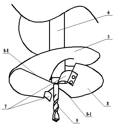
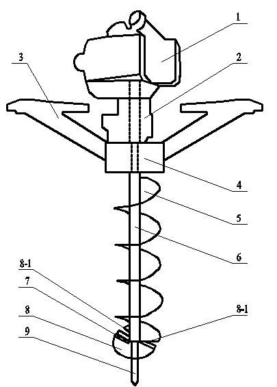
[0007] Specific implementation mode one: combine figure 1 with figure 2 Illustrate the present embodiment, the portable optical cable marking embedding drill of the present embodiment comprises gasoline engine 1, speed reducer 2, support seat 4, helical blade 5, drill rod 6, drill bit 9 and two handrails 3, the gasoline engine 1 The output end is fixedly connected with the input end of the reducer 2, and the lower end surface of the reducer 3 is fixedly installed with a bearing seat 4, and the upper end of the drill rod 6 is fixedly connected with the output end of the reducer 2 through the support seat 4, and the drill rod 6 is fixedly connected with the output end of the reducer 2. The lower end is fixedly equipped with a drill bit 9, and the helical blade 5 is fixedly connected on the wall of the drill rod 6, and the helical blade 5 is located between the support base 4 and the drill bit 9, and two handrails 3 are installed on the outer wall of the support base 4.

[0008...

specific Embodiment approach 2

[0009] Specific implementation mode two: combination figure 1 with figure 2 The present embodiment will be described. The drill 9 of the present embodiment is an alloy drill. So set, the service life is longer. Other components and connections are the same as those in the first embodiment.

specific Embodiment approach 3

[0010] Specific implementation mode three: combination figure 1 with figure 2 The present embodiment will be described. The blade thickness of the helical blade 5 of the present embodiment is 2 mm to 5 mm. Such a setting prevents the deformation of the spiral blade and has a longer service life. Other compositions and connections are the same as those in Embodiment 1 or Embodiment 2.


PUM


Abstract

The invention discloses a portable optical cable identifying embedded hole boring device, and relates to an optical cable identifying embedded hole boring device. The hole boring device solves the problems of high operation cost, long operation time, low efficiency, large operation area, large negative loss and large operation error existing in the condition that manual work is adopted in the pit digging operation in embedding the optical cable identification. The output end of a gasoline engine (1) is fixedly connected with the input end of a reducer (2); a supporting seat (4) is fixedly arranged on the lower end surface of the reducer (3); the upper end of a drill stem (6) is fixedly connected with the output end of the reducer (2) passing through the supporting seat (4); an aiguille (9) is fixed arranged at the lower end of the drill stem (6); a helical blade (5) is fixedly connected on the wall of the drill stem (6), and is positioned between the supporting seat (4) and the aiguille (9); and two railings (3) are arranged on the outer wall of the supporting seat (4). The hole boring device is suitable for optical cable identifying embedded operation.

Description

technical field [0001] The invention relates to a drilling device for embedding optical cable markings, in particular to a portable drilling device for embedding optical cable markings. Background technique [0002] At present, the excavation work in the burial of all optical cable markers in China is carried out manually. The main problems of manual work are: 1. High operating cost. Based on the labor cost of 120 yuan per person per day, the cost of each operation pit is 6-12 yuan. 2. The operation time is long and the efficiency is low. According to the sampling survey, the average time for manual work is 10-25 minutes per pit (depending on the soil quality and the technical level of the operators). 3. The operation area is large and the negative loss is large. Since most of the optical cable identification burying operations are in farmland or forest areas, the manual excavation area is large, and it is easy to damage the crops and trees near the operation pit, resulti...

Claims


Application Information

Patent Timeline
Patent Type & Authority Applications(China)
IPC IPC(8): E21B3/00E21B17/22E21B10/43
Inventor 张熹
Owner 张熹
Why Eureka
Try Eureka