Lens cone and camera lens module thereof

A lens barrel and barrel body technology, which is applied in the field of lens modules, can solve the problems of large friction between the lens barrel and the lens base, burrs, and easy generation of chipping, so as to improve assembly accuracy and reliability, and reduce chipping. Possibility, effect of reducing friction

Inactive Publication Date: 2010-10-27
HONG FU JIN PRECISION IND (SHENZHEN) CO LTD +1
View PDF0 Cites 6 Cited by
  • Summary
  • Abstract
  • Description
  • Claims
  • Application Information

AI Technical Summary

Problems solved by technology

However, the lens barrel and lens base in the current lens module are all injection molded. Since the plastic material is easily deformed, and it is difficult to control the precise molding of the threads on the lens barrel and lens base during the molding process, the lens will The assembly and cooperation between the barrel and the lens base is not smooth, and there are defects such as errors and burrs between the threads of the lens barrel and the lens base, so that the friction between the lens barrel and the lens base is relatively large, and it is easy to produce chips during the matching process. These debris falling on the sensor surface of the lens module will seriously affect the imaging quality of the lens module

Method used


Image

  • Lens cone and camera lens module thereof
  • Lens cone and camera lens module thereof
  • Lens cone and camera lens module thereof

Examples


Embodiment Construction

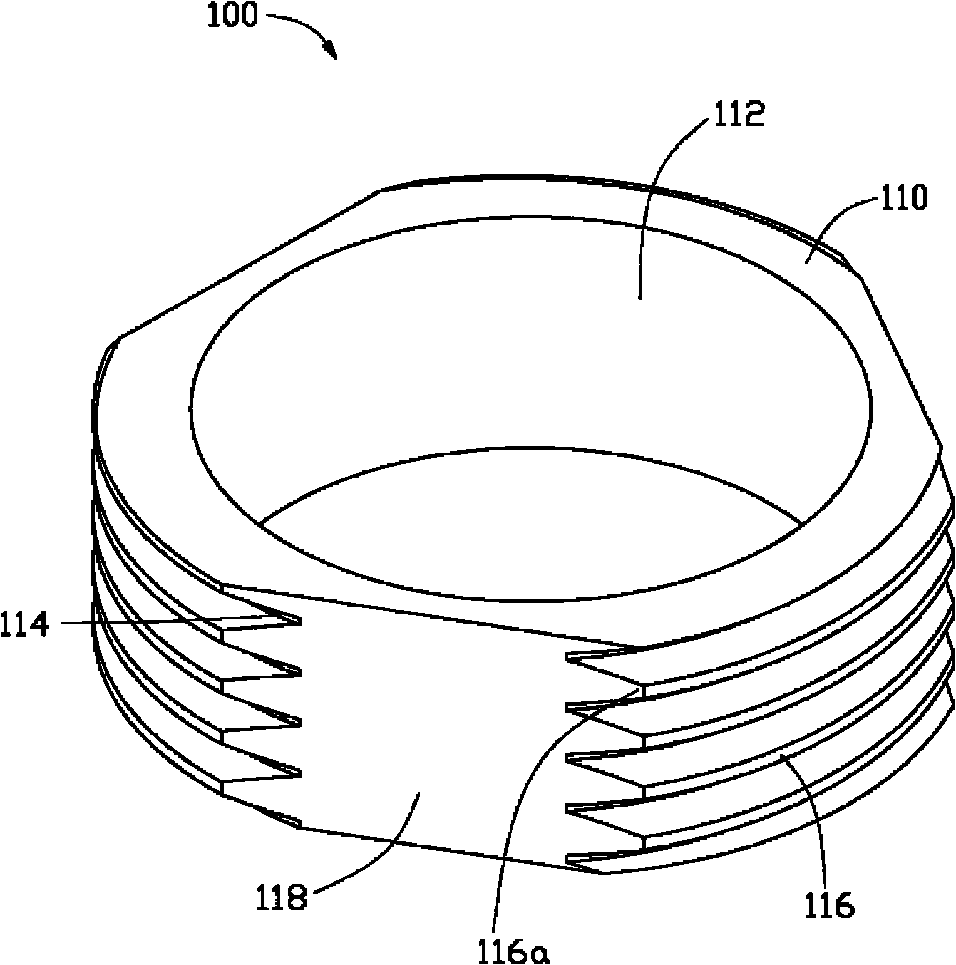
[0012] see figure 1 , a lens barrel 100 provided by the first preferred embodiment of the present invention. The lens barrel 100 includes a barrel body 110 , and the barrel body 110 is in the shape of a hollow cylinder and includes an outer side surface 112 and an inner side surface 114 . An external thread 116 surrounding the barrel 110 is formed on the outer side surface 112 of the barrel 110 . On the outer side surface 112 of the barrel body 110 , three chord sections 118 are formed at equal intervals to separate the outer threads 116 .

[0013] The chord cut surface 118 is formed by cutting the cylinder body 110 along the axis parallel to the cylinder body 110 with three equally spaced and equal length chords in the circumference formed by the outer side surface 112 as the starting point. The three chord sections 118 divide the external thread 116 on the barrel 110 into three symmetrically discontinuous main thread areas 116a. Preferably, the central angle of the main t...


PUM


Abstract

A lens cone comprises a hollow columnar cone body which comprises an outer side wall and an inner side wall. External threads around the cone body are formed on the outer side wall of the cone body. Three tangential sections for separating the external threads are arranged on the outer side wall of the cone body at equal intervals. The lens cone and the camera lens module thereof of the invention utilize three tangential sections to separate the tangential sections on the outer side wall of the cone body so as to decrease the area of the threads, decrease the friction generated in the process of assembling the lens cone, as well as reduce the impurities like deckle edge formed on the threads and decrease the possibility of generating dropped crumbs, therefore promoting the assembling precision and the reliability in the assembling process of the lens cone. The invention also provides a camera lens module using the lens cone.

Description

technical field [0001] The invention relates to a lens barrel, and also relates to a lens module applying the lens barrel. Background technique [0002] The existing lens module includes a lens seat and a lens barrel screwed into the lens seat. The mirror base includes an accommodating cavity, and an inner thread is arranged on the inner wall of the accommodating cavity. An outer thread is provided on the outer wall of the lens barrel, and the outer thread of the lens barrel and the inner thread of the lens seat are screwed with each other, so that the lens barrel is fixed in the accommodating cavity of the lens seat. However, the lens barrel and lens holder in the current lens module are all injection-molded. Since the plastic material is easily deformed, and it is difficult to control the precise molding of the threads on the lens barrel and the lens holder during the molding process, this will make the lens The assembly of the barrel and the lens seat is not smooth, and...

Claims


Application Information

Patent Timeline
Patent Type & Authority Applications(China)
IPC IPC(8): G02B7/02H01L27/146
Inventor 何鸿隆
Owner HONG FU JIN PRECISION IND (SHENZHEN) CO LTD
Why Eureka
Try Eureka