
Method and device for estimating length of transmission line

A technology for estimating devices and transmission lines, which is applied in the field of estimating the length of transmission lines in Ethernet, which can solve the problems of expensive hardware, pulse signals that cannot conform to Ethernet specifications, and reflection signals that cannot be detected

Inactive Publication Date: 2010-10-27
LINK TECH INC
View PDF6 Cites 5 Cited by
  • Summary
  • Abstract
  • Description
  • Claims
  • Application Information

AI Technical Summary

Problems solved by technology

[0006] Since the signal length of the incident pulse signal is shortened, the energy of the incident pulse signal is also reduced. Therefore, when the distance between the end of the transmission line and the transmitting end is long, the conventional technology cannot detect the reflected signal due to energy attenuation.
In addition, the shortened pulse signal cannot meet the specifications of the Ethernet standard and requires additional hardware to generate

Method used

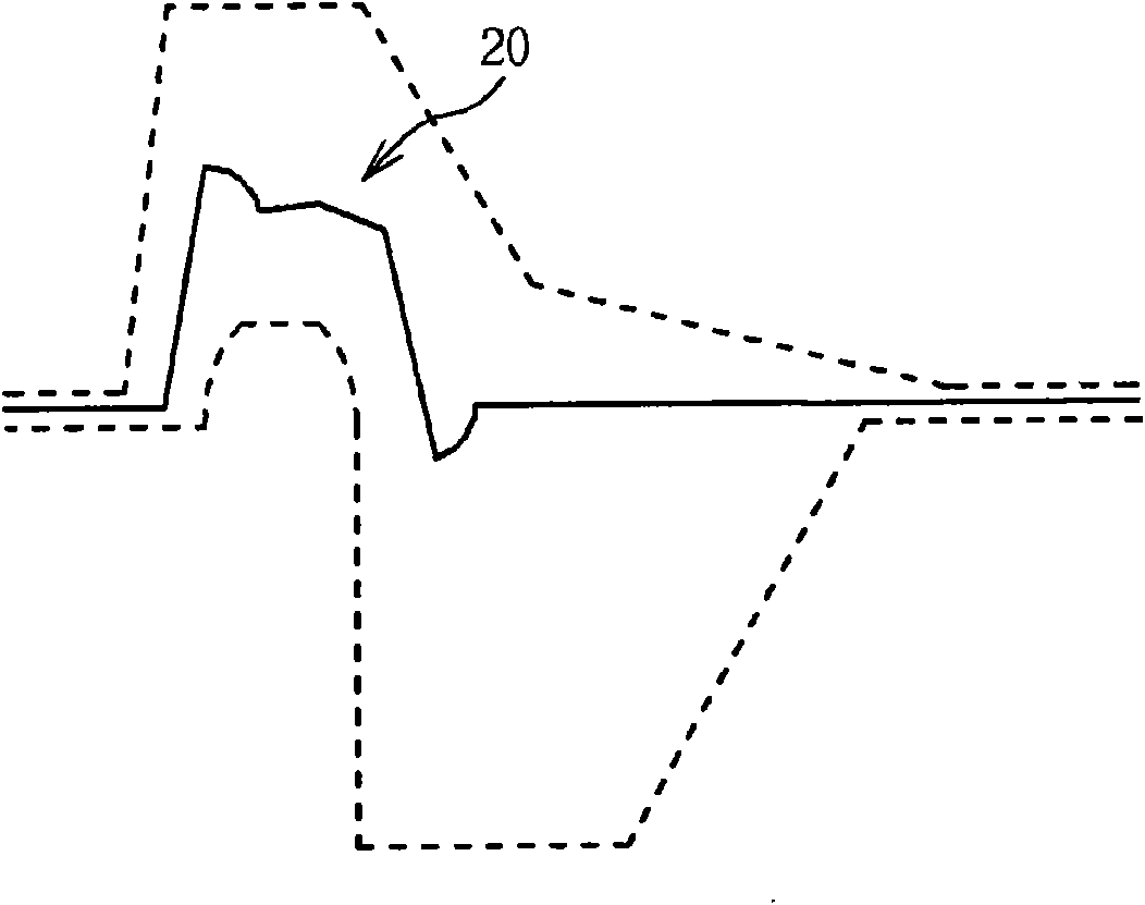
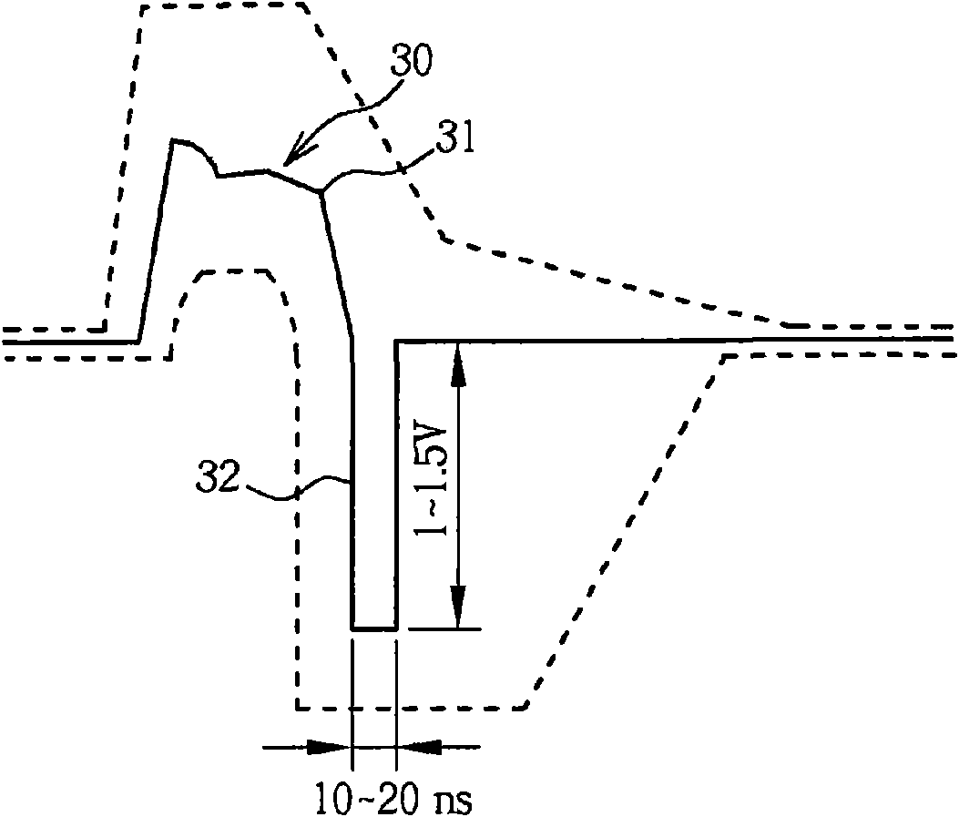

Image

  • Method and device for estimating length of transmission line
  • Method and device for estimating length of transmission line
  • Method and device for estimating length of transmission line

Examples


Embodiment Construction

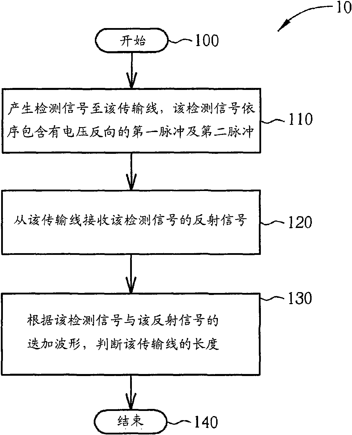
[0032] Please refer to figure 1 , figure 1 It is a schematic diagram of the process 10 of the embodiment of the present invention. Process 10 is used to estimate the length of the transmission line for Ethernet, which includes the following steps:

[0033] Step 100: Start.

[0034] Step 110: Generate a detection signal to the transmission line. The detection signal sequentially includes a first pulse and a second pulse with a reverse voltage.

[0035] Step 120: Receive the reflection signal of the detection signal from the transmission line.

[0036] Step 130: Determine the length of the transmission line according to the superimposed waveform of the detection signal and the reflection signal.

[0037] Step 140: End.

[0038] According to the process 10, the embodiment of the present invention generates a detection signal with a first pulse and a second pulse to the transmission line. Wherein, the first pulse and the second pulse have reverse voltages. Next, the embodiment of the pres...


PUM


Abstract

The invention relates to a method for estimating the length of a transmission line, which comprises the steps of: generating a detecting signal to the transmission line, wherein the detecting signal sequentially comprises a first pulse and a second pulse which have reverse voltages; receiving a reflecting signal of the detecting signal from the transmission line; and judging the length of the transmission line according to a superposed waveform of the detecting signal and the reflecting signal. The name of the invention is method and device for estimating the length of the transmission line.

Description

Technical field [0001] The present invention relates to a method for estimating the length of a transmission line and related devices, and more particularly to a method for estimating the length of a transmission line and related devices for Ethernet. Background technique [0002] Ethernet (Ethernet) is a network hardware standard that follows the IEEE 802.3 protocol, and has been widely used in regional networks. According to different needs, Ethernet devices can be connected through a variety of different network media, such as twisted pair, coaxial cable, and optical fiber, etc., to support tens of millions of bits per second (10Mbps) , One hundred million bits per second (100Mbps) and one billion bits per second (1Gbps) and other bit rate modes. [0003] At present, most of the Ethernet devices are usually connected through twisted pair cables, and support two bit rate modes of 10Mbps and 100Mbps. At the beginning of the network connection, two interconnected Ethernet devices...

Claims


Application Information

Patent Timeline
IPC IPC(8): H04B3/46H04B3/40
Inventor 林冠亨吴宗轩侯文生
Owner LINK TECH INC
Learn More