Method and device for single plate dislocation of metal plate laminates

A metal sheet, sheet metal technology, applied in transportation and packaging, object separation, thin material handling, etc., can solve the problems of unreliable handling, not compact enough, long travel of parts, etc., to achieve flexible selection of transmission mechanism, prevent diameter To the effect of poor rigidity and simple and compact device

Inactive Publication Date: 2012-07-18
陈石云
View PDF0 Cites 0 Cited by
  • Summary
  • Abstract
  • Description
  • Claims
  • Application Information

AI Technical Summary

Problems solved by technology

[0002] Many automatic feeding devices are used to transport workpieces in the existing sheet metal stamping process. These devices separate a piece from the sheet metal stack. At present, vacuum chucks or magnetic suction parts are directly used. Although these devices are widely used, there are some disadvantages. : It is unreliable to deal with the two pieces sticking together due to oil stains. The application of the sheet with a hole in the middle is limited. The flatness of the sheet is strictly required. The need for frequency work; there is also a step structure at the bottom of the sheet metal stack to push the single sheet through the narrow slot to achieve single sheet separation. Although this scheme can reliably separate the single sheet, but for larger-sized sheet-like sheets, The movement stroke of the parts that push the sheet material separation movement is long, especially the radial rigidity of the large-sized thin sheet material is poor, and the process of pushing the sheet material is prone to failure. The application of the sheet material with a hole in the middle is limited, and the structural size of the entire separation device and The motion stroke is affected by the size of the sheet material, which is poor in versatility and not compact enough to meet the needs of high-frequency work

Method used


Image

  • Method and device for single plate dislocation of metal plate laminates
  • Method and device for single plate dislocation of metal plate laminates
  • Method and device for single plate dislocation of metal plate laminates

Examples


specific Embodiment 1

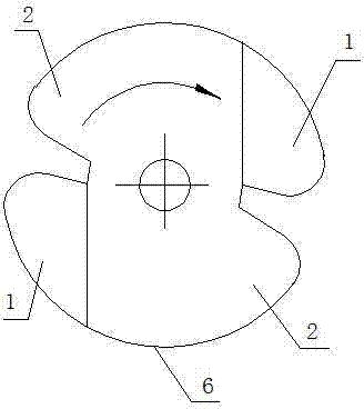
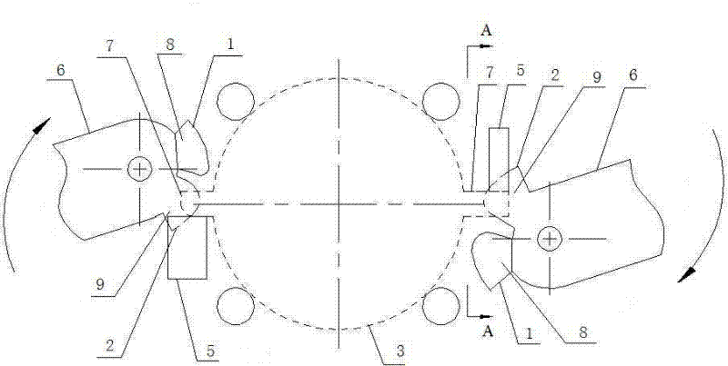
[0039] Adopt two dials 6 to displace the bottom sheet 4 of sheet stack 3, its working process is as follows: image 3 , Figure 4 , Figure 5 and Image 6 As shown, the height of the part used to move the single piece of sheet material 4 is smaller than the thickness of the sheet when the sideways toggle pendulum block 1 starts to pick the tabs, and the sideways toggle pendulum block 1 works with the stopper 5, which can effectively prevent Misplaced excess sheet.

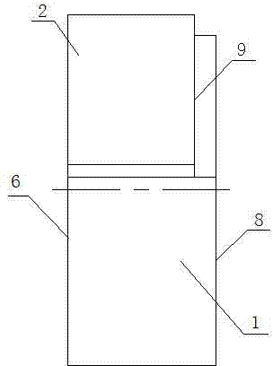
[0040] First, the flange portion 7 of the sheet stack 3 is placed on the contact surface 9 (see image 3 and Figure 4 ),according to image 3 Rotate the turntable 6 in the direction, and move the pendulum block 1 sideways to move the flange part 7 of the bottom single sheet material 4 to rotate and displace, so that the flange part 7 of the bottom single sheet material 4 gradually rotates away from the axial limit pendulum block 2 (see Figure 5 ), the contact surface 8 gradually enters under the flange par...

specific Embodiment 2

[0043] Reference as Figure 7 , Figure 8 , Figure 9 and Figure 10 As shown, two pairs of lateral toggle pendulum block 1 and axial limit pendulum block 2 are used to rotate according to the direction shown in the figure, and the lateral toggle pendulum block 1 is used to toggle the uppermost outer single sheet of sheet material stack 3 4 Make it rotate misaligned with the rest of the sheet material stacks 3 . Its working process is as follows.

[0044] The outer peripheral portion of the sheet material is polygonal, and the junction of two adjacent outer edges has a protruding portion connected to the contact surface 9. When the turntable 6 is rotated, the contact surface 9 of the axial limit pendulum block 2 is separated from the single sheet material 4. , the contact surface 8 of the pendulum block 1 is pressed against the protruding part of the rest of the sheet metal stacks 3 (see Figure 9 and Figure 10 ), the stopper 5 descends together with the dial 6.

[004...

specific Embodiment 3

[0047] refer to Figure 11 , Figure 12 and Figure 13 As shown, use two pairs of lateral toggle pendulum 1 and axial limit pendulum 2 to rotate in the direction shown in the figure, and lateral toggle pendulum 1 to toggle the outermost sheet 4 of the slanted sheet stack Make it and sheet material stack 3 translation dislocation. Its working process is as follows.

[0048] The outer peripheral portion of the sheet material is polygonal, and the junction of two adjacent outer edges has a protruding portion connected to the contact surface 9. When the turntable 6 is rotated, the contact surface 9 of the axial limit pendulum block 2 is separated from the single sheet material 4. , when the contact surface 8 of the pendulum block 1 is moved laterally against the protrusions of the rest of the sheet stacks 3; when the turntable 6 is continued to be rotated, the contact surface 8 of the pendulum block 1 is separated from the rest of the sheet stacks 3 , the contact surface 9 of ...


PUM


Abstract

The invention relates to a method and a device for single plate dislocation of metal plate laminates. The device comprises a lateral toggling swing block; an axial spacing swing block is arranged along the swinging direction of the lateral toggling swing block; the axial spacing swing block is linked with the lateral toggling swing block and is used for retaining a plate at the end of a dischargeend, and the axial spacing swing block can prevent the plate laminates from moving axially along the discharge end; the lateral toggling swing block is used for toggling a single plate at the end of the discharge end to dislocate the plate with other plate laminates and disengage the axial end surface of the plate from the axial spacing swing block, and thus, the single plate can be completely separately from other plate laminates in the subsequent procedures. By the method, the single plate can be dislocated from the plate laminates effectively. The device can effectively solve the problem of dislocated redundant plates occurring in the process of single plate dislocation. The single plate dislocated by using a parallel dislocation mode and a rotary dislocation mode has the advantages ofsimple and compact structure, high generality, flexible application and high efficiency.

Description

technical field [0001] The invention relates to a method and a device for single-piece dislocation of sheet metal stacks, which are suitable for the field of stamping processing of sheet metal. Background technique [0002] Many automatic feeding devices are used to transport workpieces in the existing sheet metal stamping process. These devices separate a piece from the sheet metal stack. At present, vacuum chucks or magnetic suction parts are directly used. Although these devices are widely used, there are some disadvantages. : It is unreliable to deal with the two pieces sticking together due to oil stains. The application of the sheet with a hole in the middle is limited. The flatness of the sheet is strictly required. The need for frequency work; there is also a step structure at the bottom of the sheet metal stack to push the single sheet through the narrow slot to achieve single sheet separation. Although this scheme can reliably separate the single sheet, but for lar...

Claims


Application Information

Patent Timeline
Patent Type & Authority Patents(China)
IPC IPC(8): B65H3/46
Inventor 陈石云
Owner 陈石云
Why Eureka
Try Eureka