Non-rope circulating multi-cabin elevator and circulating system thereof

A circulatory system, multi-car technology, applied to elevators, lifts, transportation and packaging in buildings, etc., can solve the problems of small number of cars in high-rise buildings, low space utilization efficiency, complex car moving mechanism, etc. Solve the effect of long waiting time and improve space utilization

Inactive Publication Date: 2010-11-03
HENAN POLYTECHNIC UNIV
View PDF1 Cites 92 Cited by
  • Summary
  • Abstract
  • Description
  • Claims
  • Application Information

AI Technical Summary

Problems solved by technology

[0003] The technical problem to be solved by the present invention is that the number of cars in high-rise buildings is small, the waiting time for the elevator is long, the car

Method used


Image

  • Non-rope circulating multi-cabin elevator and circulating system thereof
  • Non-rope circulating multi-cabin elevator and circulating system thereof
  • Non-rope circulating multi-cabin elevator and circulating system thereof

Examples


Embodiment 1

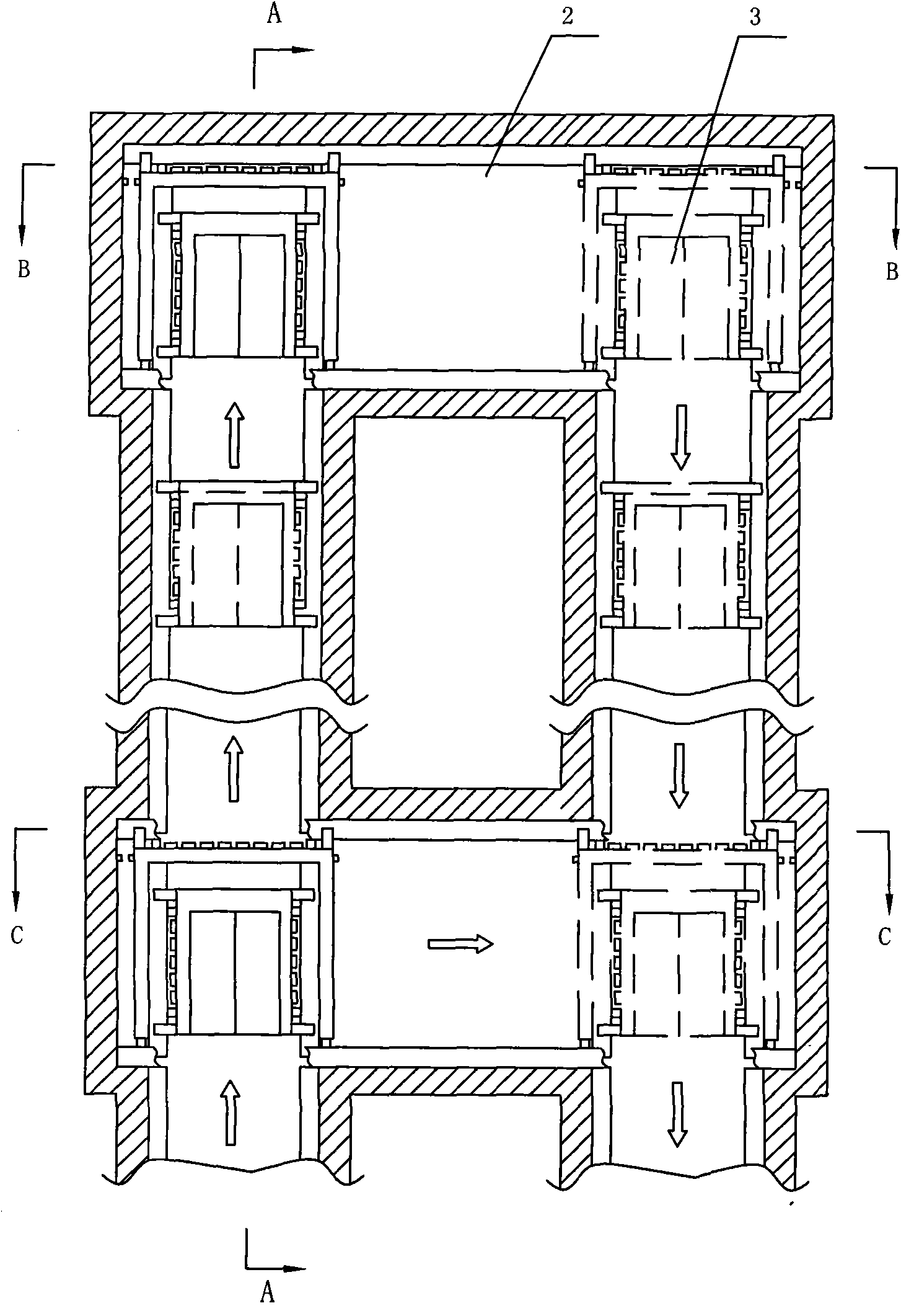
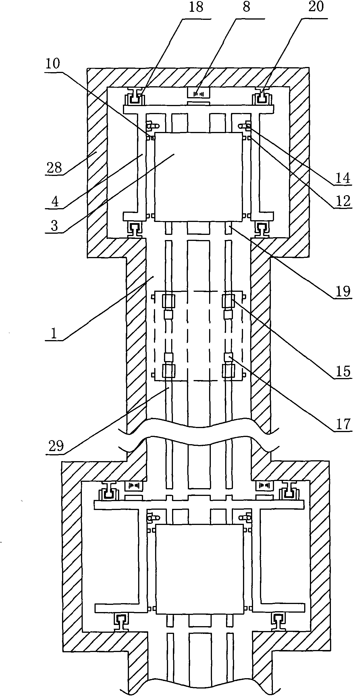
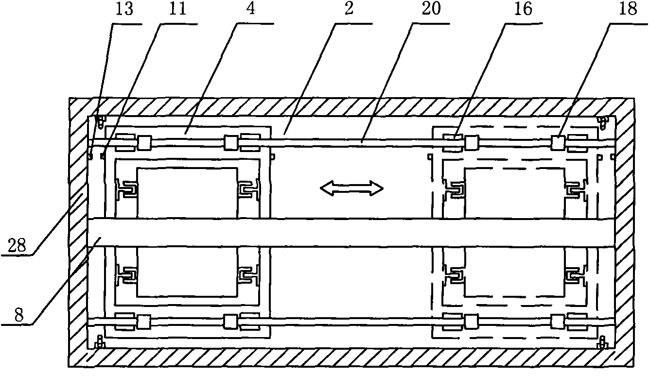
[0037] Such as figure 1 , 2 , Shown in 3 and 4, a kind of cordless circulation multi-car elevator, comprises vertical shaft 1 and car 3, fixed lifting guide rail II 29, lifting power mechanism and control system in the vertical shaft. The lifting power mechanism is a permanent magnet linear motor 6 arranged between the car 3 and the shaft wall 28 . A horizontal shaft 2 is set on the vertical shaft; a mobile frame 4 is installed in the horizontal shaft 2, and the lifting guide rail Ⅰ19 is fixed on the mobile frame 4, and the lifting guide rail Ⅰ19 and the lifting rail Ⅱ29 are jointed with a slot; the corresponding permanent magnet in the vertical shaft The linear motor 6 and the permanent magnet linear motor 6 in the moving frame are jointed with a seam; a moving frame transfer mechanism is arranged in the horizontal shaft. The moving frame transfer mechanism is a fixed translation guide rail I20 inside the horizontal shaft, and a translation guide shoe 18 is arranged outside...

Embodiment 2

[0040] Such as Figure 5 , 6 As shown, the moving frame transfer mechanism is a rotating arm arranged in the horizontal shaft. The rotating arm includes a rotating motor 25 fixed on the horizontal shaft, a gear 31 is fixed on the output shaft of the rotating motor 25, and the gear 31 meshes with the ring gear 32 fixed on the rotating shaft 26. In the upper bearing 33, the connecting frame 27 is fixed on the rotating shaft 26, and one end of the connecting frame 27 is fixed on the mobile frame 4 one side, and other structures are the same as embodiment 1.

[0041] After the car and the mobile frame are fixed together, the rotary motor 25 starts to work, and the gear 31 on the output shaft of the rotary motor 25 drives the rotating shaft 26 to rotate through the ring gear 32, and the rotating shaft 26 drives the mobile frame and the car to rotate, so that the car can be rotated in different positions. The transfer in the vertical well shaft, other modes of operation are the sa...

Embodiment 3

[0043] Such as Figure 7 , 8 , 9, the moving frame transfer mechanism is an annular turret arranged in the horizontal shaft. The horizontal shaft of the annular turret is fixed with a translation guide rail II30, and a translation guide shoe 18-1 is arranged outside the translation guide rail II30. The translation guide shoe 18-1 is fixed on the mobile frame 4, and the translation brake 16-1 is fixed on the mobile frame 4; Arc linear motor 8-1 is arranged between frame 4 and horizontal shaft 2, and its structure is the same as embodiment 1.

[0044]After the car and the moving frame are fixed together, the arc-shaped linear motor 8-1 starts to be energized to drive the moving frame to slide along the translation guide rail II 30, and other operating modes are the same as in embodiment 1. When the car is transferred from one vertical shaft to another vertical shaft, another mobile frame moves to the original vertical shaft to prepare for the next transfer of the car. With su...


PUM


Abstract

The invention discloses a non-rope circulating multi-cabin elevator and a circulating system thereof and relates to the field of non-rope elevators. The non-rope circulating multi-cabin elevator comprises a vertical shaft, wherein an elevating guide rail is fixed inside the vertical shaft and is connected with a cabin, an elevating power mechanism and a control system; an elevating guide rail II is fixed inside the vertical shaft; a horizontal shaft is arranged on the vertical shaft; a movable frame is arranged inside the horizontal shaft; an elevating guide rail I is fixed on the movable frame; the elevating guide rail I and the elevating guide rail II are in seamed butt joint; a movable frame transfer mechanism is arranged inside the horizontal shaft; the movable frame is driven by a translational power source; and an elevating brake and an elevating guide roller are fixed on the cabin. Through the technical scheme of the invention, the problem of waiting for the elevator in a high-rise building for a long time is solved; the building space is rationally arranged and the space utilization ratio of the elevator is effectively improved.

Description

technical field [0001] The invention belongs to the field of cordless elevators, and in particular relates to a cordless circulation multi-car elevator and a circulation system thereof. Background technique [0002] In the prior art, the lifting and lowering of the elevator are all completed in one shaft, and in the elevator with this structure, only one car is allowed to exist in each shaft. In a limited building area, the number of elevator shafts is certain, and each shaft corresponds to a car. For the use of very high floors, the problem is that there are too few cars and the waiting time for the elevator is long. In the prior art, the car is suspended on the cross bar, and the linear motor mover as the power source adopts a hinge structure for turning. The disadvantages are: the driving structure is complicated, the car is difficult to fix, and it is easy to shake during operation. Patent application No. 03138115.4 discloses an elevator installation with a plurality o...

Claims


Application Information

Patent Timeline
IPC IPC(8): B66B9/02B66B11/04B66B1/30B66B1/32
Inventor 汪旭东许孝卓封海潮袁世鹰上官璇峰司纪凯张志华王旭强
Owner HENAN POLYTECHNIC UNIV
Why Eureka
Try Eureka