Image forming apparatus

An image and image recording technology, which is applied in the direction of electric recording process applying charge pattern, equipment of electric recording process applying charge pattern, electric recording technique, etc., can solve the problems of image quality deterioration, device distortion, etc. Effects of image deviation, distortion reduction, and positional deviation reduction

Active Publication Date: 2010-11-03
FUJIFILM BUSINESS INNOVATION CORP
View PDF10 Cites 6 Cited by
  • Summary
  • Abstract
  • Description
  • Claims
  • Application Information

AI Technical Summary

Problems solved by technology

[0002] In image forming apparatuses of related art such as copiers and printers, techniques disclosed in the following Patent Documents 1 to 5 are known as techniques for solving the problem that the apparatus breaks down due to unevenness of the ground. image quality is degraded due to distortion

Method used


Image

  • Image forming apparatus
  • Image forming apparatus
  • Image forming apparatus

Examples


Embodiment Construction

[0047] Hereinafter, exemplary embodiments of the present invention will be described with reference to the drawings. However, the present invention is not limited to the following exemplary embodiments.

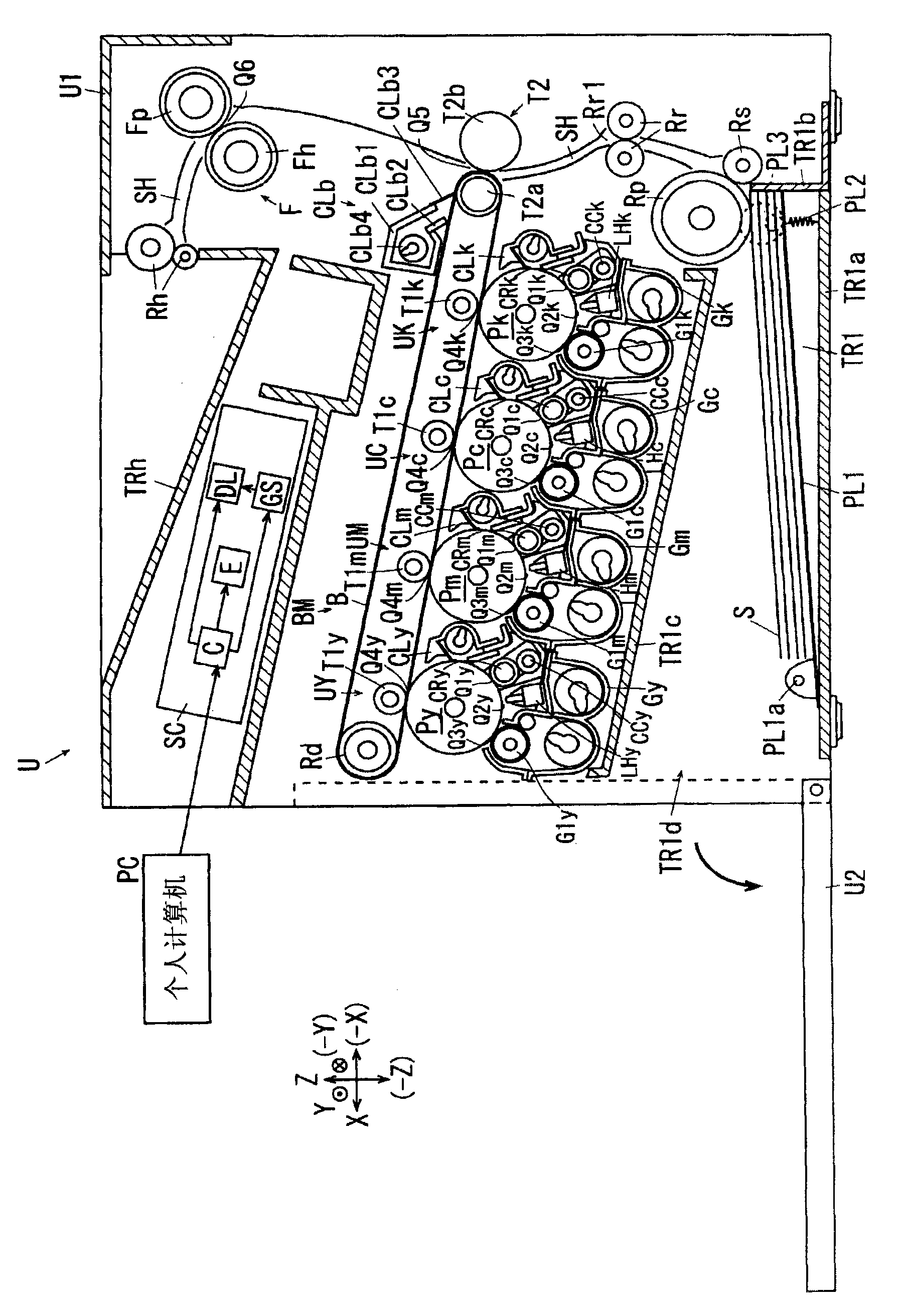
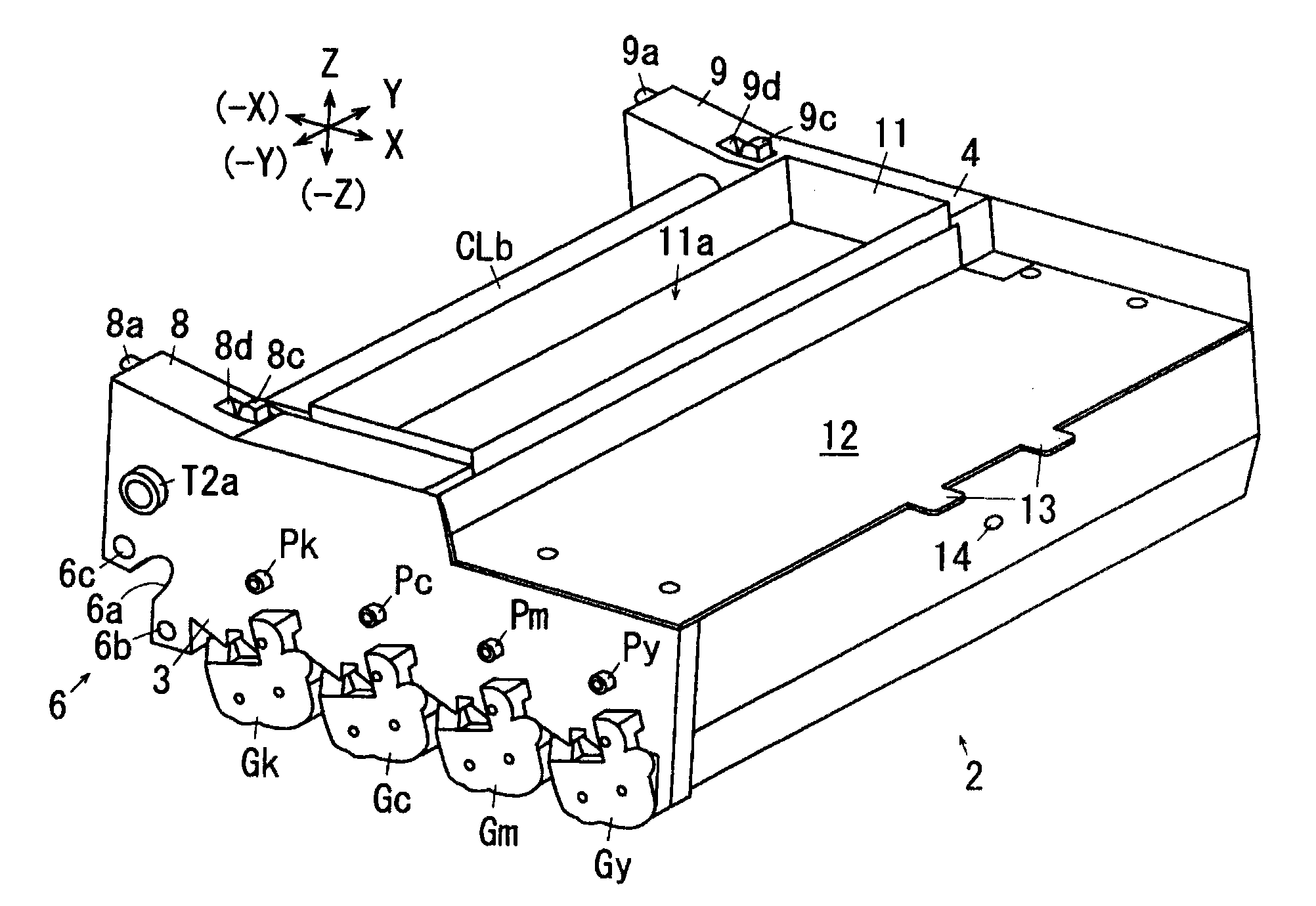
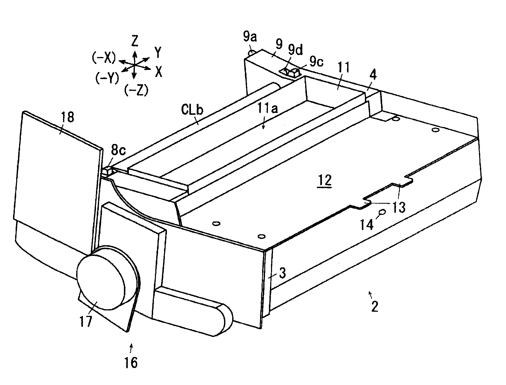
[0048] In order to facilitate the understanding of the following description, in the figure, the X-axis direction, the Y-axis direction and the Z-axis direction are respectively defined as the front-rear direction, the left-right direction and the up-down direction, and the arrows X, -X, Y, -Y, Z, The direction or side represented by -Z is defined as front or front, rear or rear, right or right, left or left, upper or upper, lower or lower, respectively.

[0049] In the drawings, a circle "○" with a dot "·" inside means an arrow pointing from the back of the paper to the front, and a circle "○" with a cross "X" inside means an arrow pointing from the front of the paper to the back.

[0050] In addition, in the drawings, components and the like that are not necessary to be de...


PUM


Abstract

An image forming apparatus includes: a medium conveyance unit; an image recording unit; and recording unit support portions. The image recording unit is supported by the medium conveyance unit in an undetachable manner for a user who uses the medium. The recording unit support portions has a first support portion and a second support portion which are disposed in the image recording unit on a side of an outlet and are spaced from each other in a width direction of a medium conveyed, and a third support portion which is disposed in the image recording unit on an opposite side to the outlet. At least the first support portion and the second support portion are supported on the side of the outlet of the medium conveyance unit.

Description

technical field [0001] The present invention relates to an image forming apparatus. Background technique [0002] In image forming apparatuses of related art such as copiers and printers, techniques disclosed in the following Patent Documents 1 to 5 are known as techniques for solving the problem that the apparatus breaks down due to unevenness of the ground. distorted, resulting in image quality degradation. [0003] Patent Document 1 (JP-A-2000-310930) discloses the following technique. In the base unit 2 are provided a paper feed roller 11, a pair of retard rollers 12, a pair of conveying rollers 13, a pair of registration rollers 14, an intermediate transfer belt 16, a secondary transfer roller 17, a fixing device 15, and a pair of Discharge rollers 19a and 19b. The base unit 2 supports the core unit 1 having four photosensitive drums 31, a charging device 32, a developing device 33, a cleaning device 34, and optical scanning systems 18Y, 18M, 18C, 18Bk by means of th...

Claims


Application Information

Patent Timeline
Patent Type & Authority Applications(China)
IPC IPC(8): G03G15/00
CPCG03G21/1695G03G2221/1684G03G2221/1654
Inventor 斋藤安秀冲村直雅小松伸能见亮太郎
Owner FUJIFILM BUSINESS INNOVATION CORP
Why Eureka
Try Eureka