Magnet switch

A magnet switch and switch technology, applied in the field of magnet switches, can solve the problems of reducing switch dustproof, oilproof and moistureproof, and achieve the effect of ordinary and cheap materials, simple structure, and convenient production and installation

Inactive Publication Date: 2010-11-03
刘伟亮
View PDF0 Cites 22 Cited by
  • Summary
  • Abstract
  • Description
  • Claims
  • Application Information

AI Technical Summary

Problems solved by technology

[0002] In the existing mechanical switches, the conductors of the exposed parts such as the contacts and the terminals of the connecting wires can c

Method used


Image

  • Magnet switch
  • Magnet switch
  • Magnet switch

Examples


Embodiment Construction

[0008] The present invention will be described in detail below in conjunction with the accompanying drawings and embodiments.

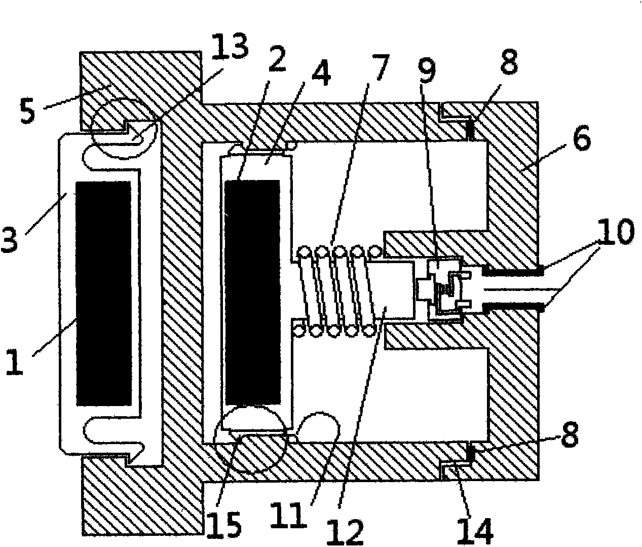
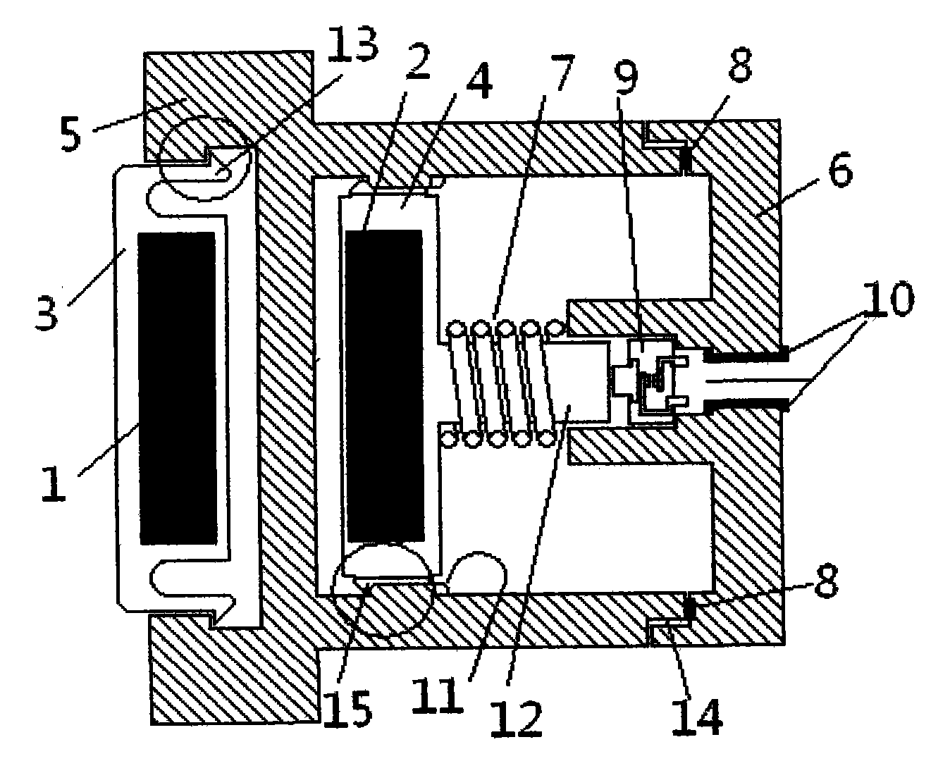
[0009] figure 1 It is an embodiment of the present invention, the active magnet 1 is embedded in the button 3 with the installation hook, and the button 3 is assembled in the concave cavity on the shell panel through the assembly force, and the concave cavity mouth has a limiting hook 13 The exit step and the bottom are designed with a position for the button 3 to move. The housing 5 is provided with a transmission part 4 embedded in the center of the driven magnet 2 with a transmission rod 12; the transmission part 4 is provided with a guide rail 15 that moves along the direction of the key force in the guide groove 11 on the inner wall of the housing 5, and the function of the guide rail 15 is to reduce resistance And prevent the transmission part 4 from rotating, so that the transmission part 4 can only move back and forth according to the key for...


PUM


Abstract

The invention discloses a magnet switch. A magnet consists of a driving magnet and a driven magnet; the driving magnet is embedded in a key with an installation clamping hook; the key is assembled on the concave cavity of the shell through an assembling force; a step for limiting the clamping hook from dropping out extends out of the mouth part of the concave cavity; and a position for the moving of the key is designed at the bottom of the concave cavity. The driven magnet is embedded in a transmission member which moves under the action of repulsive force or attractive force of the driving magnet; the transmission member is provided with a guide rail which slides in a guide groove on an inner wall of the shell along the direction of a key pressing force. The magnet switch comprises the working processes that the repulsive force of the magnets between the key and the transmission member passes through the shell and overcomes the resetting force of a spring to enable a transmission rod to mover towards a rear cover to drive the transmission rod to press a switch; and when the pressing force disappears, the resetting spring ejects the transmission member back to a resting position. A sealing ring is arranged between the rear cover and the shell, and the rear cover and the shell are connected into a whole by adopting a threaded structure; and the rear cover is provided with the switch and a lead seal-off bushing of a lead wire of the switch, and therefore, the magnetic switch can work under water.

Description

technical field [0001] The invention relates to an electric switch, in particular to a magnet switch which realizes isolation by transmitting the force of a button between magnets. Background technique [0002] In existing mechanical switches, bare conductors such as contacts and terminals of connecting wires can contact air through the gap between the key and the casing, thereby reducing the dustproof, oilproof and moistureproof capabilities of the switch. Contents of the invention [0003] The content of the present invention is a magnet switch that realizes isolation by transmitting the force of the button between the magnets. A magnet switch includes a button 3 embedded in an active magnet 1, a panel with a concave cavity inner wall with a guide groove 5 and a center. The back cover 6 of the opening casting switch lead wire: it is characterized in that, the casing 5 is provided with a transmission part 4 embedded in the center of the driven magnet 2 with a transmission...

Claims


Application Information

Patent Timeline
IPC IPC(8): H01H36/00
Inventor 刘伟亮
Owner 刘伟亮
Why Eureka
Try Eureka