
Solar energy storage system and method

A technology of an energy storage system and an energy storage method, applied in the field of solar energy storage systems, can solve the problems of high charging voltage, unsatisfactory charging and low charging voltage of solar panels, etc., and achieve the effect of improving the utilization rate

Inactive Publication Date: 2010-11-03
STATE GRID CORP OF CHINA +1
View PDF9 Cites 21 Cited by
  • Summary
  • Abstract
  • Description
  • Claims
  • Application Information

AI Technical Summary

Problems solved by technology

[0003] However, directly using the electric energy generated by the solar panel to charge the battery pack is also greatly affected by the intensity of sunlight. If the intensity of sunlight is high, the charging voltage provided by the solar panel will be high; The charging voltage is lower
However, the batteries in the existing battery packs all adopt a fixed charging connection method, which greatly restricts the application of solar energy storage systems. For example, charging battery packs in series requires a higher input voltage. If the input voltage of the storage battery is insufficient, it is easy to cause insufficient charging and reduce the utilization rate of solar energy; the parallel charging of battery packs has lower requirements on the input voltage, but the voltage difference between the storage batteries may lead to reverse flow between the storage batteries. charging phenomenon, so the charging efficiency is low

Method used


Image

  • Solar energy storage system and method
  • Solar energy storage system and method
  • Solar energy storage system and method

Examples


Embodiment Construction

[0019] The present invention will be described in detail below in conjunction with the accompanying drawings.

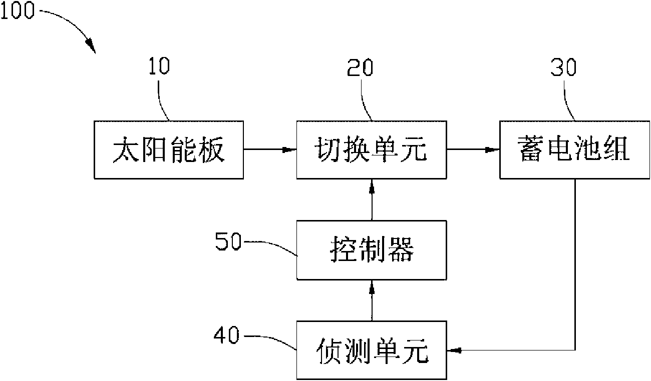
[0020] see figure 1 , shows a functional block diagram of a solar energy storage system 100 provided in a preferred embodiment of the present invention. The solar energy storage system 100 includes a solar panel 10, a switching unit 20 connected to the solar panel 10, a storage battery pack 30 connected to the switching unit 20, and a battery pack 30 connected to the solar panel 10 and the storage battery. A detection unit 40 connected to the group 30 , and a controller 50 connected to the detection unit 40 and the switching unit 20 .

[0021] The solar panel 10 is used to convert solar energy into electrical energy and output the converted electrical energy. In this embodiment, the solar panel 10 is a photovoltaic silicon panel.

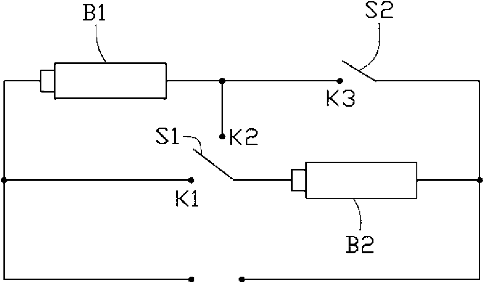
[0022] The switching unit 20 is used to switch the charging mode of the batteries in the battery pack 30. The switching unit 20 has a p...


PUM


Abstract

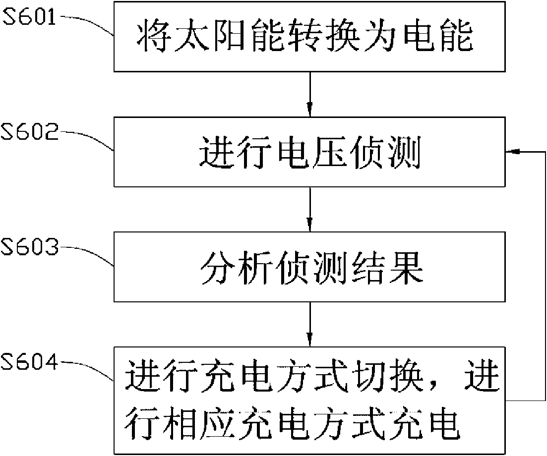
The invention relates to a solar energy storage system comprising a solar panel, a switching unit, a storage battery pack, a detecting unit and a controller. The solar panel is used for transforming the solar energy into the electric energy; the switching unit is used for switching the charging mode of storage batteries in the storage battery pack; the storage battery pack is used for storing the energy; the detecting unit is used for detecting the charging voltage of the solar panel and the open-circuit voltage of the storage battery pack; and the controller is used for controlling the switching unit to be switched into the corresponding charging connecting circuit to charge the storage battery pack with the corresponding charging mode according to the detection result of the detecting unit. The requirement of the storage battery pack for the charging voltage can be reduced when the intensity of the sunlight is not high enough, thus the storage battery pack can still be charged, and the utilization rate of the solar energy can be improved effectively. The invention also relates to a solar energy storage method.

Description

technical field [0001] The present invention relates to an energy storage system and method, in particular to a solar energy storage system and method. Background technique [0002] With the advancement of science and technology, solar energy has been widely used in all aspects of production and life. Since the application of solar energy is affected by factors such as weather and light intensity, the output of electric energy directly obtained by photoelectric conversion is extremely unstable. Therefore, the solar energy storage system generally stores the electric energy obtained by solar photoelectric conversion in a battery pack first, and then The electric equipment is powered by the battery pack, so that a stable supply of electric energy can be realized. [0003] However, directly using the electric energy generated by the solar panel to charge the battery pack is also greatly affected by the intensity of sunlight. If the intensity of sunlight is high, the charging v...

Claims


Application Information

Patent Timeline
Patent Type & Authority Applications(China)
IPC IPC(8): H02J7/00H02J7/35H02N6/00
CPCH01M10/465H01M16/00H02J7/35Y02E60/10
Inventor 赖志成
Owner STATE GRID CORP OF CHINA
Learn More