Circular glass numerical control edging machine

A technology of edge grinding machine and glass, which is applied in the direction of machine tools suitable for grinding the edge of workpieces, parts of grinding machine tools, grinding machines, etc. It can solve the problems of low control precision, poor roundness of the glass periphery, and poor positioning effect. Achieve the effect of high glass precision, uniform roundness and high speed

Inactive Publication Date: 2010-11-10
张家港市恒久玻璃机械有限公司
View PDF6 Cites 10 Cited by
  • Summary
  • Abstract
  • Description
  • Claims
  • Application Information

AI Technical Summary

Problems solved by technology

[0002] In the prior art, when grinding the edge of round glass, a special-shaped edging machine is generally used to process round glass. This type of edging machine generally adopts the following two processing methods: the first method is through Completely manual processing, one hand rotates the glass table, the other hand controls the grinding wheel, and the glass is ground entirely by the feeling of the hand. In this way, the hand controls the lightness and weight of the grinding wheel, not only the positioning effect is poor, and the edge of the grinding Unevenness, poor roundness around the glass, and long processing cycle, high labor intensity of the operator, it is difficult to process high-precision glass; the second method has been improved compared to the first method, through the pressure of the cylinder Drive the grinding wheel to grind the edge of the glass. Although it is separated from the completely manual processing, this method still has the disadvantage of low control accuracy. Not only is the glass prone to edge bursting, but also the roundness is poor. Round glass edger with high cutting precision and easy operation

Method used


Image

  • Circular glass numerical control edging machine
  • Circular glass numerical control edging machine
  • Circular glass numerical control edging machine

Examples


Embodiment Construction

[0017] The present invention will be further described below in conjunction with accompanying drawing and embodiment:

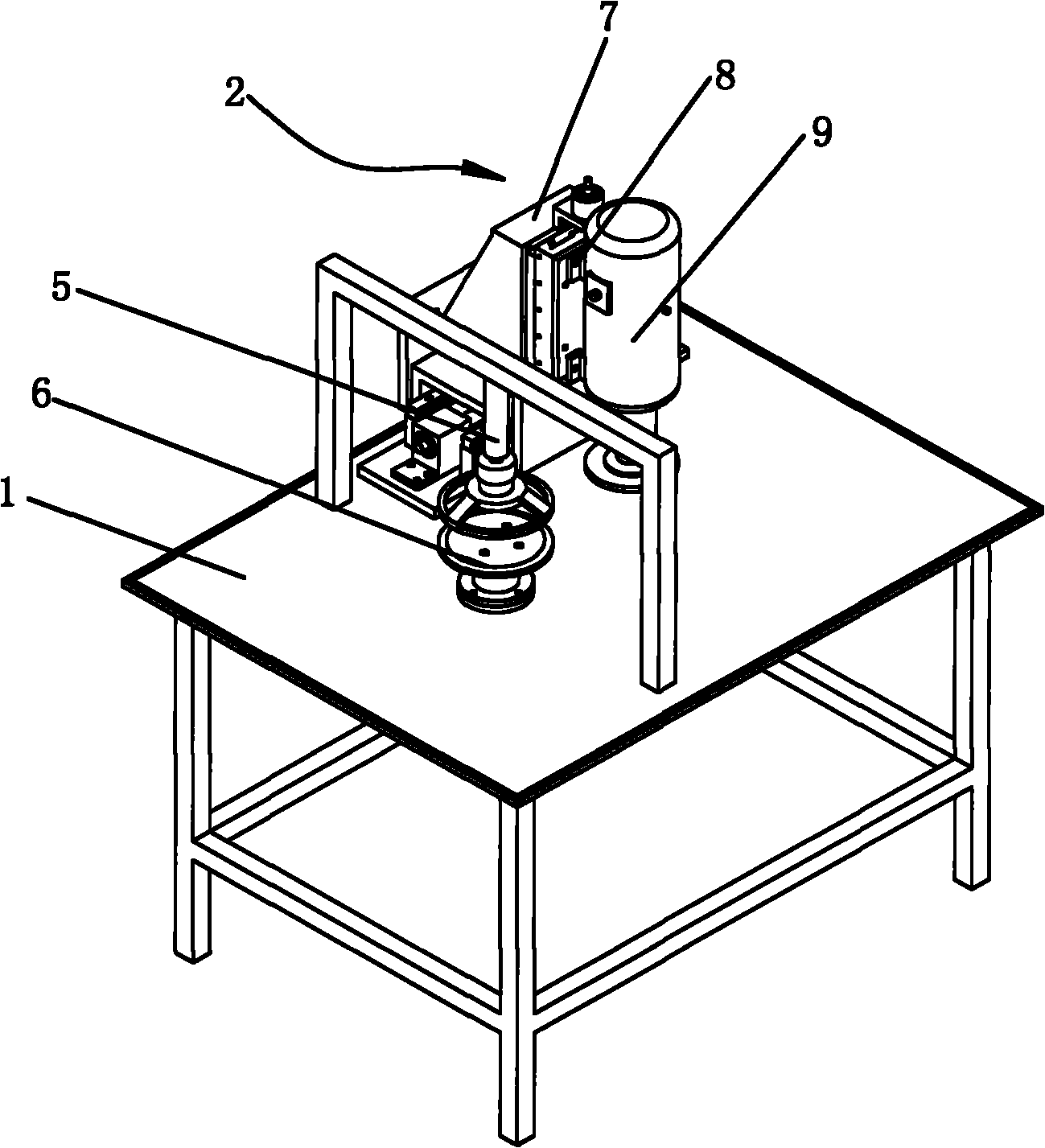
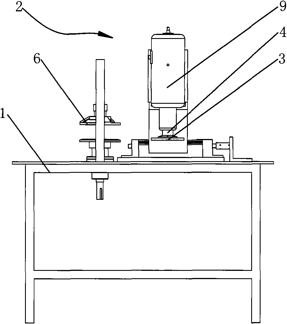
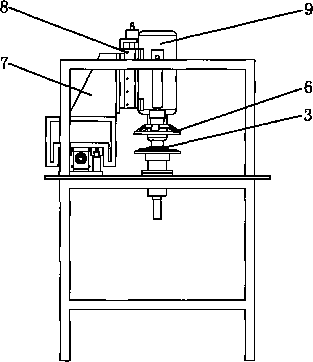
[0018] Such as Figure 1-5 A circular glass numerical control edging machine shown includes a workbench 1 and a grinding mechanism 2 arranged on the workbench 1. The grinding mechanism 2 includes an edging wheel 3 and a wheel for driving the edging wheel 3 to rotate. The main rotating shaft 4, the ball screw used to drive the edging wheel 3 for horizontal feeding, the workpiece rotary shaft 5 for driving the glass to be edged to rotate, the servo motor for driving the ball screw for horizontal feeding, and A power unit that drives each shaft in rotation.

[0019] The grinding mechanism 2 also includes a frame body 7, a sliding part 8 that is movably arranged on the frame body 7, the edging wheel 3 is placed on the sliding part 8, and the ball screw is arranged on the frame body 7 and is connected to the sliding part 8 in transmission. . The sliding part 8 ...


PUM


Abstract

The invention relates to a circular glass numerical control edging machine. The machine comprises a work bench and a grinding mechanism arranged on the work bench. The grinding mechanism comprises an edging wheel, a main rotating shaft, a ball screw, a workpiece revolving shaft, a servo motor and a power unit, wherein the main rotating shaft is used for driving the edging wheel to rotate; the ball screw is used for driving the edging wheel to perform horizontal feed; the workpiece revolving shaft is used for driving glass to be edged to revolve; the servo motor is used for driving the ball screw to perform the horizontal feed; and the power unit is used for driving each shaft to rotate. The invention designs equipment special for edging circular glass. The tool setting and the edging of the edging wheel are controlled by adopting a numerical control operating system, so that mechanized glass has the characteristics of high precision, uniform roundness, high speed and low cost.

Description

technical field [0001] The invention relates to the field of glass edging, in particular to a circular glass numerical control edging machine. Background technique [0002] In the prior art, when grinding the edge of round glass, a special-shaped edging machine is generally used to process round glass. This type of edging machine generally adopts the following two processing methods: the first method is through Completely manual processing, one hand rotates the glass table, the other hand controls the grinding wheel, and the glass is ground entirely by the feeling of the hand. In this way, the hand controls the lightness and weight of the grinding wheel, not only the positioning effect is poor, and the edge of the grinding Unevenness, poor roundness around the glass, and long processing cycle, high labor intensity of the operator, it is difficult to process high-precision glass; the second method has been improved compared to the first method, through the pressure of the cyl...

Claims


Application Information

Patent Timeline
IPC IPC(8): B24B9/08B24B41/04B24B41/00B24B47/20
Inventor 刘一平刁徐林严红夏
Owner 张家港市恒久玻璃机械有限公司
Why Eureka
Try Eureka