Tape package of chip components and preparation method and device thereof

A technology for preparing devices and components, which is applied in the directions of packaging, transportation and packaging, and sending objects, and can solve the problems of unable to tear the tape normally, high bonding force between the tape and the carrier tape, etc.

Inactive Publication Date: 2010-11-10
GUANGDONG FENGHUA ADVANCED TECH HLDG
View PDF4 Cites 8 Cited by
  • Summary
  • Abstract
  • Description
  • Claims
  • Application Information

AI Technical Summary

Problems solved by technology

[0006] In order to solve the above problems, the purpose of the present invention is to provide a kind of braided packaging of chip components, which solves the problem of paper scraps sticking to the adhesive tape after the tape is torn when the electronic components of the braided package are placed on the placement machine. The bonding force between the tape and the carrier tape is too high and the tape cannot be torn off normally

Method used


Image

  • Tape package of chip components and preparation method and device thereof
  • Tape package of chip components and preparation method and device thereof
  • Tape package of chip components and preparation method and device thereof

Examples


preparation example Construction

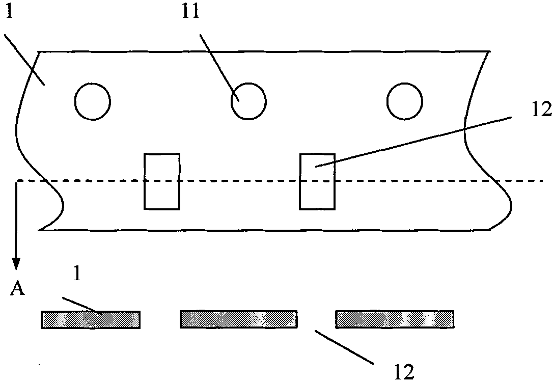
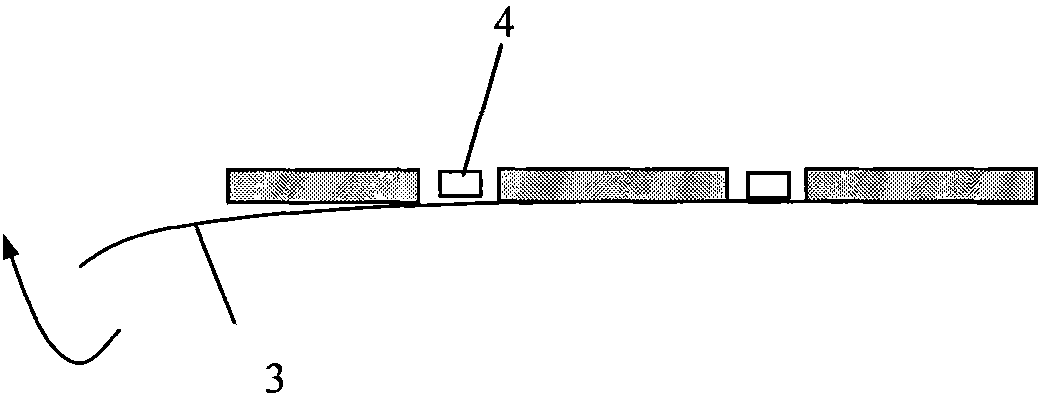
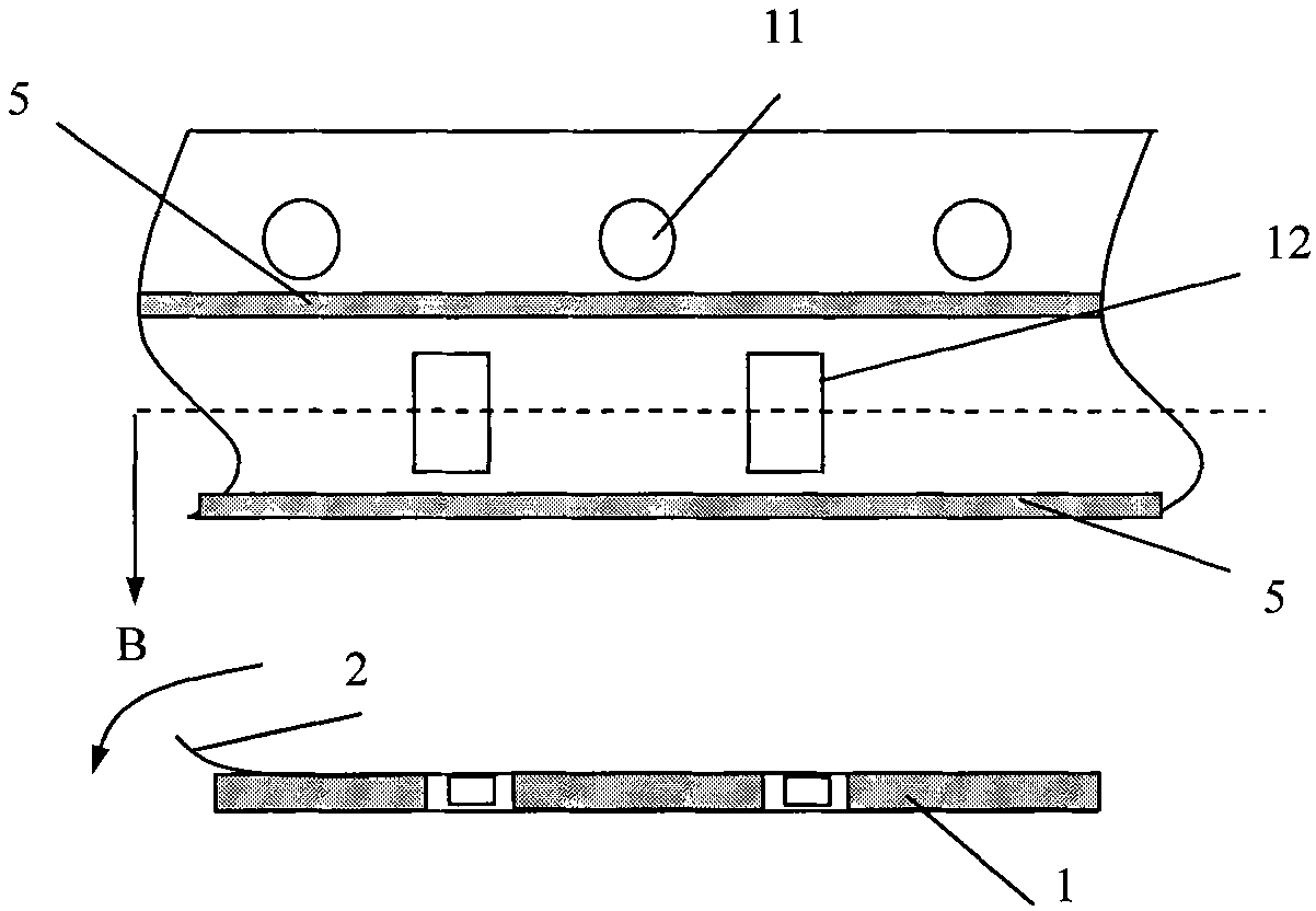
[0029] The preparation method of the braided packaging of the above-mentioned chip components includes the following steps: first, put the chip components 4 into the square hole 12 of the back-sealed carrier tape 1; then seal the upper surface of the carrier tape 1 with an adhesive tape 2 , and two easy-tear lines 6 parallel to the joint site 5 are set on the inner side of the joint site 5 . The easy-to-tear line 6 is formed by scraping, punching or laser technology.

[0030] Or, the preparation method of the braided packaging of the above-mentioned chip components includes the following steps: first, put the chip components 4 into the square hole 12 of the back-sealed carrier tape 1; The adhesive tape 2 of the tearing line 6 seals the upper surface of the carrier tape 1 , and the two parallel easy-tearing lines 6 are located at the inner side of the bonding portion 5 of the adhesive tape 2 and the carrier tape 1 after sealing.

Embodiment 1

[0033] like Figure 5 As shown, the cross section of the heating block 7' of the original tape braiding machine is designed to be concave, and the protrusions on the left and right sides are heating contact surfaces, which are used to heat the tape, so that the tape 2 and the carrier tape 1 are fused to form two parallel heating Traces, i.e. binding sites5.

[0034] This embodiment improves the braiding machine heating block on the original basis, as Image 6 As shown, two slightly protruding scrapers 71 are added on the inner side of the heating contact surface of the heating block 7, and the scrapers are required to be too high so as not to completely cut off the adhesive tape. In this way, when the heating block 7 is in use, the adhesive tape 2 and the carrier tape 1 move under the heating block 7, and the heating block 7 forms two thin lines at the inside of the joint 5 while forming two heating traces to bond the adhesive tape and the carrier tape. Groove, i.e. easy tea...

Embodiment 2

[0036] like Figure 5 As shown, the cross section of the heating block 7' of the original tape braiding machine is designed to be concave, and the protrusions on the left and right sides are heating contact surfaces, which are used to heat the tape, so that the tape 2 and the carrier tape 1 are fused to form two parallel heating Traces, i.e. binding sites5.

[0037] like Figure 7 As shown, in this embodiment, on the basis of the original equipment, a pair of pin wheels 8 or dotted line cutting hobs are installed behind the original heating block 7', and the heating contact surface between the pin wheels 8 or dotted line cutting hobs and the heating block Parallel inside. Like this, when adhesive tape 2 moves below heating block 7 ' and pin wheel 8, will pull pin wheel 8 to rotate. Pin wheel 8 will pierce a large amount of thin pinholes on the adhesive tape in the process of rotation, and these thin pinholes are connected into two rows of parallel dotted lines.


PUM


Abstract

The invention discloses a tape package of chip components and a preparation method and device thereof. The invention is characterized by additionally arranging two easily torn lines parallel to the binding site at the inner side of an adhesive tape on the binding site of a carrier tape and the adhesive tape in the tape package by remaking heating blocks of a taping machine or splitting cutters of an adhesive tape splitter. No adhesive force exists between the torn part of the adhesive tape and the carrier tape, thus avoiding that the adhesive tape sticks the paper scraps or can not be torn, and the taping process can adapt to wider heating temperature range and stripping force range, and the taped products can adapt to wider temperature and humidity storage environment, thus not affecting normal use of the tapes.

Description

technical field [0001] The invention belongs to the field of chip components, in particular to a braided package of chip components, a preparation method and a device for the braided package. Background technique [0002] The braiding packaging of existing chip components is to form circular guide holes 11 and square holes 12 on the carrier tape 1 respectively (see figure 1 ), and then seal the square hole 12 with the bottom tape 3 under the carrier tape 1 (except that the carrier tape 1, the square hole 12, and the bottom tape 3 are formed at the same time or are integrally formed), and the chip components 4 are pressed by a tape braiding machine. It is required to put it into the square hole 12 (see figure 2 ), then seal the top of the square hole 12 with adhesive tape 2 on the top of the carrier tape 1 (see image 3 ). Both the adhesive tape 2 and the bottom tape 3 are coated with hot-melt adhesive, and the adhesive tape 2, the bottom tape 3 and the carrier tape 1 are...

Claims


Application Information

Patent Timeline
Patent Type & Authority Applications(China)
IPC IPC(8): B65D73/02B65B15/04B65H35/02
Inventor 谭正伦张俊雷攀峰张远生杨晓平陈柏青
Owner GUANGDONG FENGHUA ADVANCED TECH HLDG
Why Eureka
Try Eureka