Coal-mining machine hydraulic system

A hydraulic system and shearer technology, which is applied to fluid pressure actuating system components, earthwork drilling, slitting machinery, etc., can solve the problems of increased shutdown rate of shearers, frequent failures, and reduced coal output, etc. Achieve the effect of reducing failure rate, reducing maintenance time, and improving operating rate

Active Publication Date: 2010-11-10
TZ COAL MINE MACHINERY
View PDF5 Cites 15 Cited by
  • Summary
  • Abstract
  • Description
  • Claims
  • Application Information

AI Technical Summary

Problems solved by technology

[0017] The present invention solves the problem that the oil temperature of the hydraulic system of the existing coal mining machine is too

Method used


Image

  • Coal-mining machine hydraulic system
  • Coal-mining machine hydraulic system
  • Coal-mining machine hydraulic system

Examples


Embodiment Construction

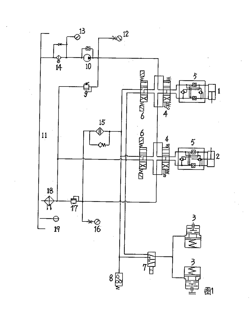
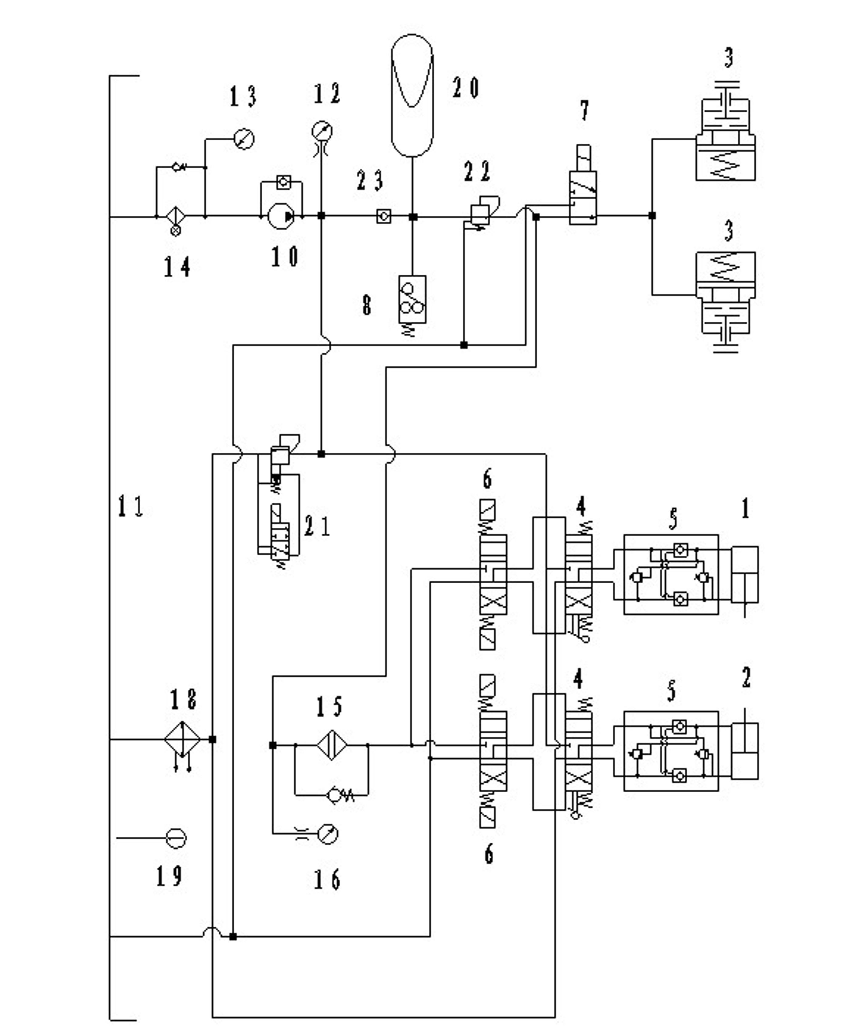
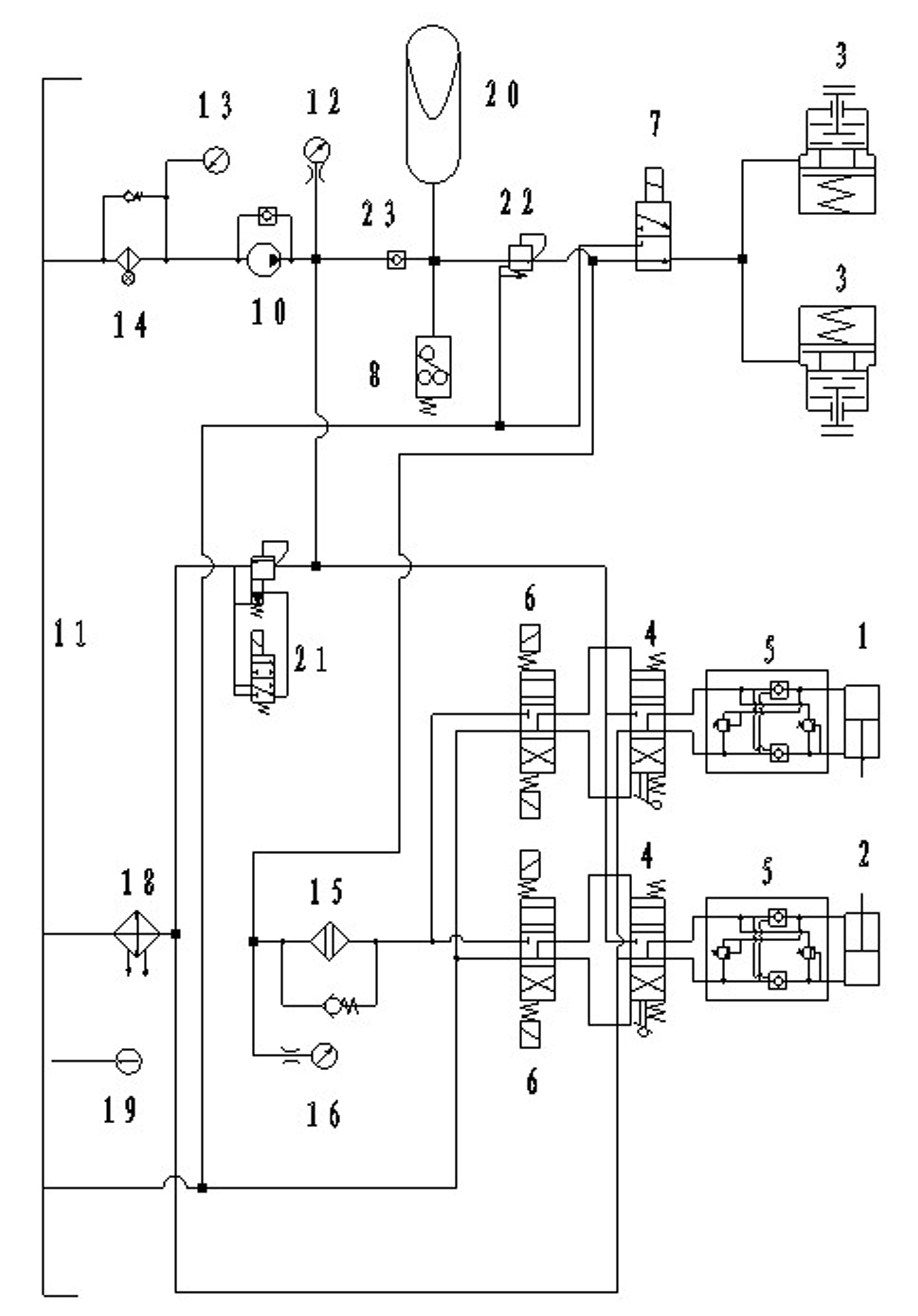
[0030] The hydraulic system of the coal mining machine includes an oil tank 11, an oil pump 10, and several oil cylinder working groups. The oil cylinder working group includes a left height-adjusting oil cylinder working group and a right height-adjusting oil cylinder working group. 1 and the hand hydraulic reversing valve and electromagnetic reversing valve connected with the left height adjustment cylinder 1, the right height adjustment oil cylinder working group includes the right height adjustment oil cylinder 2 and the hand hydraulic reversing valve and electromagnetic reversing valve connected with the right height adjustment oil cylinder 2 The valve is characterized in that the outlet of the oil pump 10 is connected to the accumulator 20, the accumulator 20 is connected to the pressure reducing valve 22, and then connected to the brake 3; the outlet of the accumulator 20 is also connected to each oil cylinder working group connected in parallel, and each oil cylinder ...


PUM


Abstract

The invention belongs to the technical field of coal-mining machines, in particular to a coal-mining machine hydraulic system solving the problems of increased outage rate and decreased coal output of a coal-mining machine because a traditional coal-mining machine hydraulic system has over-high oil temperature and high failure frequency. In the coal-mining machine hydraulic system of the invention, an oil pump outlet is connected with an accumulator which is connected with a pressure-reducing valve and then connected with a brake, the outlet of the accumulator is also connected with oil cylinder working units mutually connected in parallel, the oil outlet of each oil cylinder working unit is directly connected with an inlet of a cooler through an oil outlet pipe, the outlet of the cooler is connected with an oil tank, and an unloading circuit is formed by the oil pump, a pilot overflowing electromagnetic reversing valve and the oil tank. The invention has the following advantages that the pump is in an unloading state when execution components are not in work, an original system works at a circulating temperature of 85-100 DEG C while the system of the invention works at 25-40 DEG C, and the original system has the million-ton coil failure time of 0.5 h while the system of the invention has the million-ton coil failure time of 1 h, therefore, it is obvious that the failure rate is reduced by 80 percent and the starting rate of the coal-mining machine is improved.

Description

technical field [0001] The invention belongs to the technical field of coal shearers, and in particular relates to a hydraulic system of a coal shearer. Background technique [0002] For a long time, 600~1200Kw electric traction shearer, the oil temperature of the pump station system is too high (about 90°C). During the underground use, hydraulic system failures occurred frequently, and finally entered the vicious cycle of repair-stop-repair-stop again, which eventually resulted in an increase in the shutdown rate of the shearer and a decrease in coal output. In addition, the frequent disassembly and assembly of the system will cause the joint seal to be damaged and the air will be brought in, which will lead to greater failure in the system. [0003] The heat generated by the hydraulic system mainly includes the power loss of the pump and motor, the overflow loss of the relief valve, the heat generated by the pressure loss of the liquid flow through the valve and the ...

Claims


Application Information

Patent Timeline
IPC IPC(8): E21C31/02F15B11/16F15B1/02F15B21/04
Inventor 樊二村
Owner TZ COAL MINE MACHINERY
Why Eureka
Try Eureka