Cutter disc of eccentric multi-shaft tunnel digging machine directly driven by hydraulic cylinders

A technology of tunnel excavation and hydraulic cylinder, which is applied in the field of cutter head of eccentric multi-axis tunnel boring machine, which can solve the problems of long axial distance of hydraulic motor + reducer, complex structure of connecting plate, high manufacturing difficulty, etc., and achieve the drive work of cutter head Reliable, low manufacturing cost, easy design and manufacture

Inactive Publication Date: 2010-11-10
SHANGHAI UNIVERSITY OF ELECTRIC POWER
View PDF5 Cites 9 Cited by
  • Summary
  • Abstract
  • Description
  • Claims
  • Application Information

AI Technical Summary

Problems solved by technology

[0003] In order to overcome the problem of long axial distance and high price of hydraulic motor + gearbox for eccentric multi-axis tunnel boring machine cutter head, or the problem of complex structure of connecting plate and high manufacturing difficulty when hydraulic cylinder is used to drive the connecting plate, The invention provides an eccentric multi-axis tunnel boring machine cutter head directly driven by a hydraulic cylinder. In addition to all the advantages of the eccentric multi-axis tunnel boring machine cutter head, the cutter head also has shorter axial distance, simpler structure and lower cost. low advantage

Method used


Image

  • Cutter disc of eccentric multi-shaft tunnel digging machine directly driven by hydraulic cylinders
  • Cutter disc of eccentric multi-shaft tunnel digging machine directly driven by hydraulic cylinders
  • Cutter disc of eccentric multi-shaft tunnel digging machine directly driven by hydraulic cylinders

Examples


Embodiment Construction

[0011] The present invention will be further described in detail in conjunction with specific implementation examples and accompanying drawings.

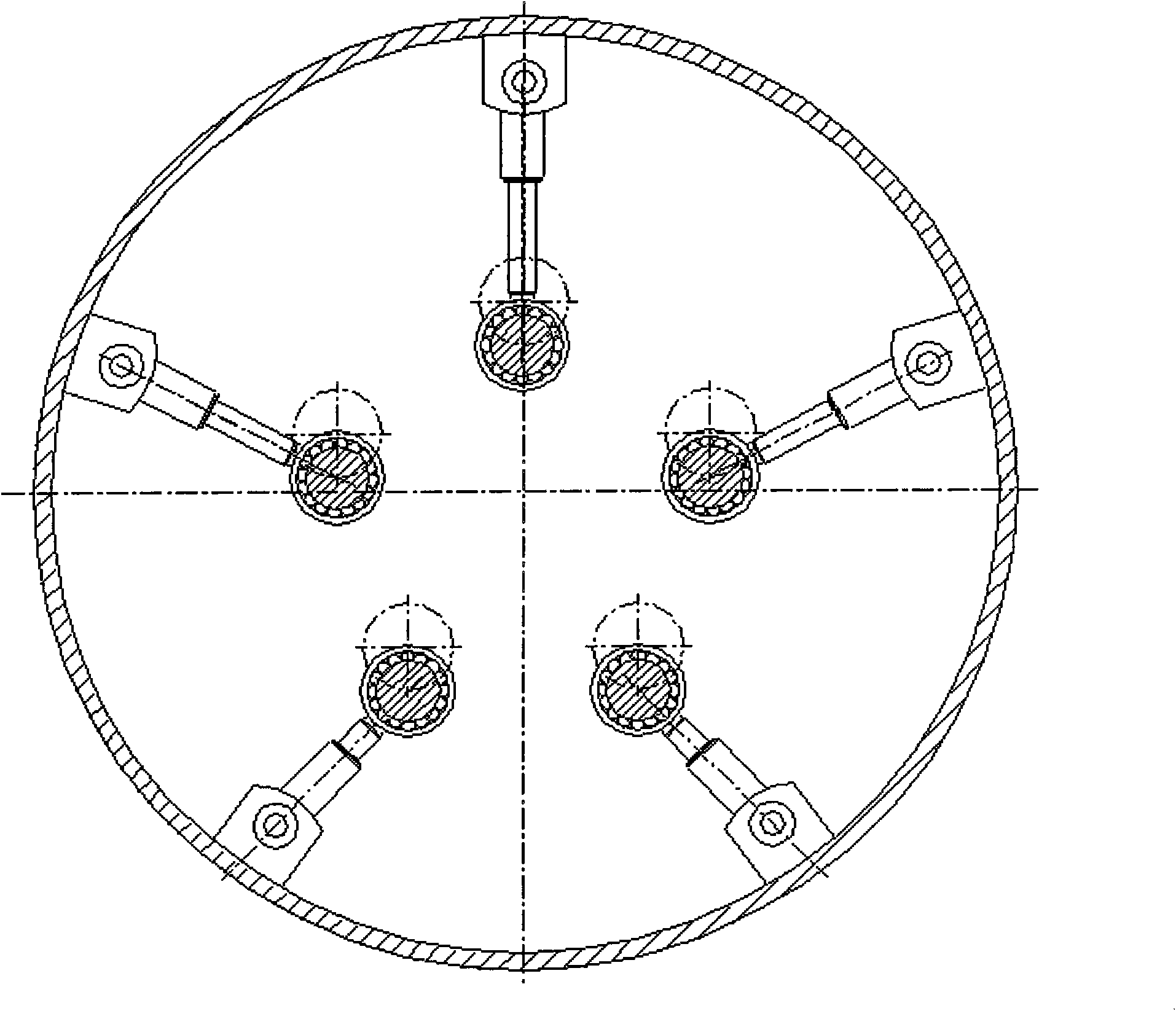
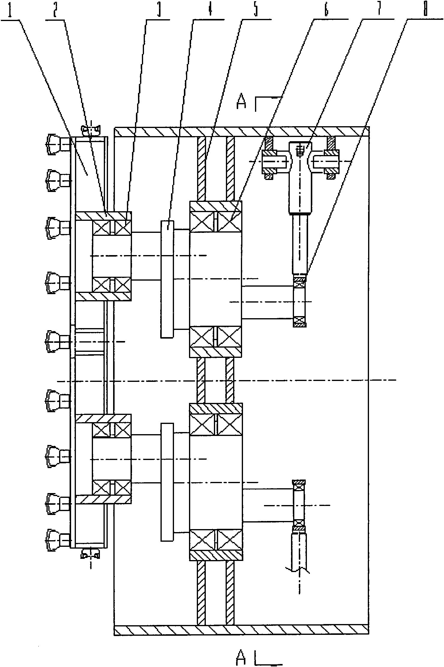
[0012] see first figure 1 , 2 Structural schematic diagram of the present invention. First install the five eccentric shafts 4 on the bearing 6 of the partition plate 5 of the roadheader casing, and then install the cutter head body 1 on the cutter head bearing 3 of the eccentric shaft, and the five eccentric shafts are along the center of the roadheader casing. Arrange evenly. The end of the hydraulic cylinder 7 is connected to the roadheader casing through a pin shaft, and the piston rod earring is installed on the joint bearing 8 of the eccentric shaft. The size and installation parameters of each hydraulic cylinder are the same, and they are evenly distributed along the circumference of the roadheader casing. The eccentric shaft 4 is a double eccentric structure, the front end is installed into the cutter head bearing sleeve 2...


PUM


Abstract

The invention relates to a cutter disc of an eccentric multi-shaft tunnel digging machine directly driven by hydraulic cylinders, which comprises a digging machine case and a disc body of the cutter disc, wherein the back side of the disc body of the cutter disc is connected five eccentric main shafts through bearings, in addition, the five eccentric main shafts are uniformly distributed along the center of the case, the middle parts of the five eccentric main shaft are supported on the bearings of a partition board of the digging machine case, the back ends of the five eccentric main shafts are respectively and directly connected with corresponding hydraulic cylinders through joint bearings, and eccentric shafts are directly driven to rotate by the hydraulic cylinders to drive the cutter disc body for carrying out rotary cutting. All hydraulic cylinders have identical dimension and installation parameters, and are arranged in the circumferential direction of the digging machine case at equal intervals. The end parts of the hydraulic cylinders are connected with the digging machine case through pin shafts, and ear rings of piston rods are arranged on the joint bearings of the eccentric shafts. Because the omission of a connecting plate, the design and the manufacture are easier, the manufacture cost is lower, the axial distance is shorter, and the stress of the cutter disc driving bearings is smaller. Because the hydraulic cylinders are adopted for driving, the cutter disc driving work is more reliable.

Description

technical field [0001] The invention relates to an eccentric multi-axis tunnel boring machine for tunnel construction, in particular to a cutter head of the eccentric multi-axis tunnel boring machine. Background technique [0002] The traditional circular tunnel boring machine adopts a single support shaft, and the motor drives the reducer (or the hydraulic motor drives the reducer) to drive the circular cutter head mounted on the support shaft to rotate and cut. Due to the shape of the cutter head and the cutting tunnel section The shape is the same, so it can only carry out the construction of circular tunnels; at the same time, due to the different cutting paths of the tools, the wear conditions are also different, so this type of roadheader is not suitable for long-distance construction. At present, the tunnel boring machine has gradually developed a new eccentric multi-axis tunnel boring machine, which adopts the method of multi-support shafts (usually four), and the sh...

Claims


Application Information

Patent Timeline
Patent Type & Authority Applications(China)
IPC IPC(8): E21D9/087
Inventor 王化更徐宝富任建兴吴懋亮
Owner SHANGHAI UNIVERSITY OF ELECTRIC POWER
Why Eureka
Try Eureka