Supercharge Your Innovation With Domain-Expert AI Agents!

Flange coiling machine

A bending machine and flange technology, applied in the field of profile forming equipment, can solve the problems of low work efficiency and poor bending effect around the flange, and achieve the effects of easy operation, ensuring aesthetics and good forming effect.

Inactive Publication Date: 2010-11-17
SHANDONG DAYE
View PDF0 Cites 1 Cited by
  • Summary
  • Abstract
  • Description
  • Claims
  • Application Information

AI Technical Summary

Problems solved by technology

[0003] The purpose of the present invention is to provide a flange bending machine to solve the problems of poor bending effect and low working efficiency around the flange

Method used


Image

  • Flange coiling machine
  • Flange coiling machine

Examples


Embodiment Construction

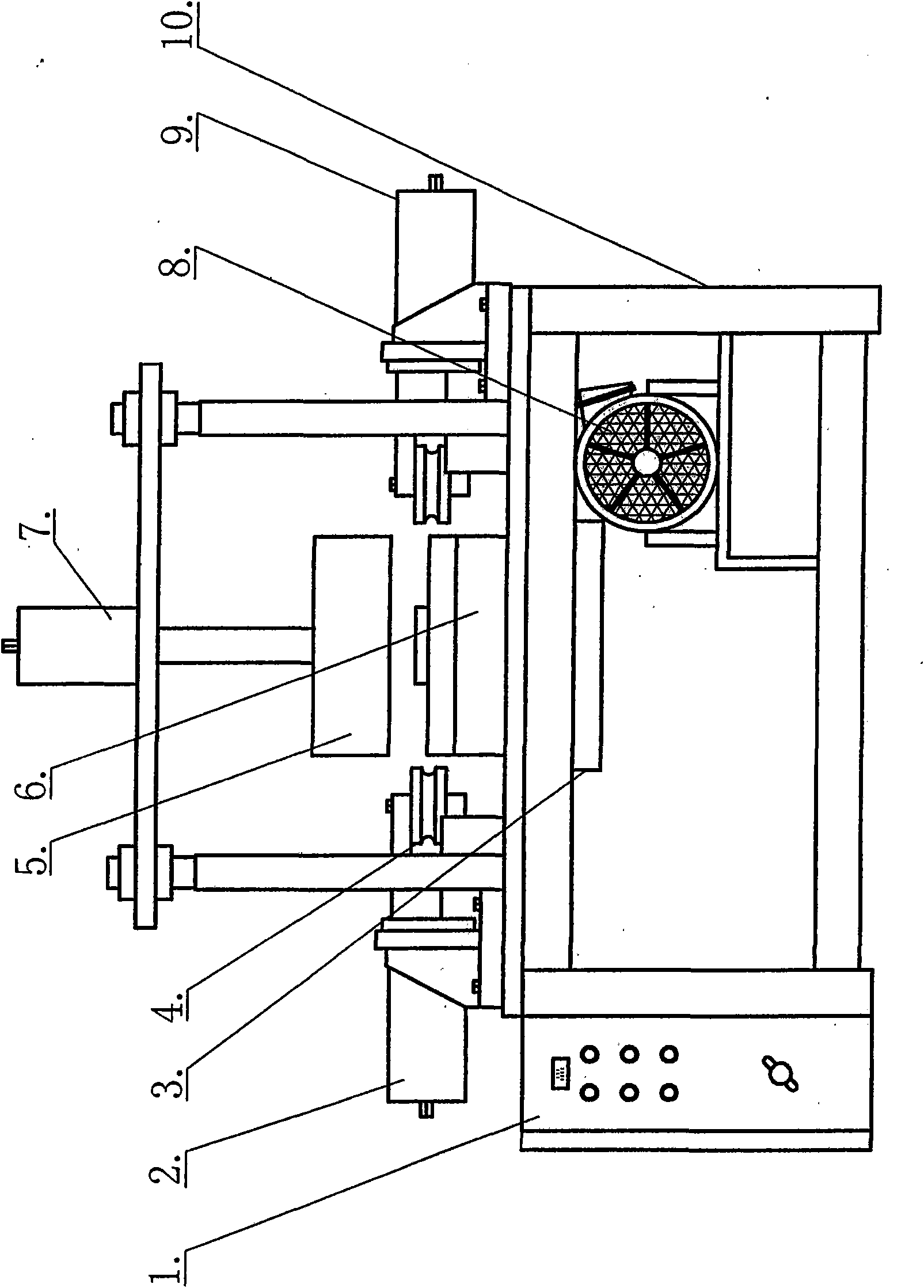
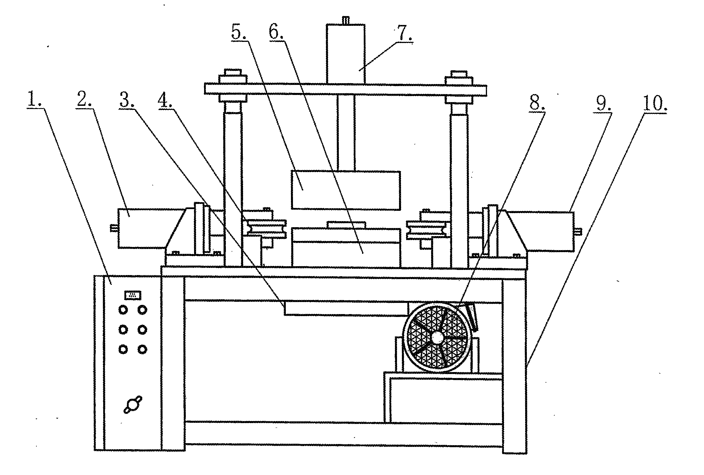
[0009] Such as figure 1 Shown, the present invention is provided with control box 1 at one end of frame 10, and motor 8 is located in frame 10, is provided with left bending oil cylinder 2 and right bending oil cylinder 9 at frame 10 tops, at one end of two bending oil cylinders respectively A volume of bending wheel 4 is provided, and the bottom of the upper compression oil cylinder 7 is provided with an upper compression disc 5 , and the lower clamping disc 6 is located on the frame 10 and corresponds to the upper compression disc 5 .

[0010] The working principle is, when working, place the processing flange on the lower clamping plate 6, start the upper clamping oil cylinder 7 to move the upper clamping plate 5 down, the flange is clamped and fixed, and the motor 8 drives the clamping through the gear box 3 The disc rotates at high speed, and then the bending wheel 4 is moved to the corresponding position through the action of the left and right bending cylinders, and the...


PUM


Abstract

The invention discloses a flange coiling machine which is characterized in that one end of a stand is provided with a control box; a motor is arranged in the stand; a left bending cylinder and a right bending cylinder are arranged on the upper part of the stand; one end of each bending cylinder is respectively provided with a coiling wheel; an upper pressing disk is arranged at the lower part of an upper pressing cylinder; and a lower pressing disk is arranged on the stand and corresponds to the upper pressing disk. By adopting the structure, the flange coiling machine has good forming effect and simple operation, ensures the coiling forming beauty of a flange, and enhances the working efficiency.

Description

technical field [0001] The invention relates to a profile forming equipment, the main function of which is to bend the periphery of a flange. Background technique [0002] When processing the I-shaped wheel, the flanges at both ends of the I-shaped wheel need to be bent and formed. At present, there is no special device for bending the flange in the profile forming equipment. With the original processing method, the bending effect around the flange is poor. Beautiful, and low work efficiency. Contents of the invention [0003] The object of the present invention is to provide a flange bending machine to solve the problems of poor bending effect and low working efficiency around the flange. [0004] In order to achieve the above object, the present invention is provided with a control box at one end of the frame, the motor is arranged in the frame, a left bending oil cylinder and a right bending oil cylinder are arranged on the upper part of the frame, and a coil bending w...

Claims


Application Information

Patent Timeline
Patent Type & Authority Applications(China)
IPC IPC(8): B21D11/10
Inventor 窦勇王金武窦万明李文军徐立娇
Owner SHANDONG DAYE
Features
  • R&D
  • Intellectual Property
  • Life Sciences
  • Materials
  • Tech Scout
  • Unparalleled Data Quality
  • Higher Quality Content
  • 60% Fewer Hallucinations
Learn More