
Laser cladding forming device and laser cladding forming method of metal part

A technology of laser cladding and metal parts, applied in the field of laser cladding molding equipment and metal parts, can solve the problems of toxicity, low strength and high surface roughness of light-cured resin, and achieve structural strength and surface The effect of high quality, reduced manufacturing costs, and simplified process flow

Active Publication Date: 2013-03-20
北京三帝科技股份有限公司
View PDF0 Cites 0 Cited by
  • Summary
  • Abstract
  • Description
  • Claims
  • Application Information

AI Technical Summary

Problems solved by technology

Disadvantages: (1) The forming process is accompanied by physical and chemical changes, so the parts are more likely to bend and need support, (2) The cost of equipment operation and maintenance is relatively high
(4) Liquid resin has odor and toxicity, and needs to be protected from light to prevent premature polymerization, and there are limitations in selection
(5) Requires secondary curing
(6) The performance of liquid resin after assimilation is not as good as that of commonly used industrial plastics. It is generally brittle and easy to break. It is not suitable for machining. The shrinkage of the resin leads to a decrease in precision, and the photocurable resin has certain toxicity, etc.
[0007] The disadvantage of the above-mentioned technology of directly melting metal forming parts is that they all adopt the powder spreading method, so no matter which form of powder is used, the metal after laser sintering has low density, porous and low strength
To improve the strength of sintered parts, post-processing must be carried out, such as impregnating resin, low melting point metal, or hot isostatic pressing, but these post-processing will change the precision of metal parts, and the surface roughness is high, and the molding efficiency is not high.

Method used

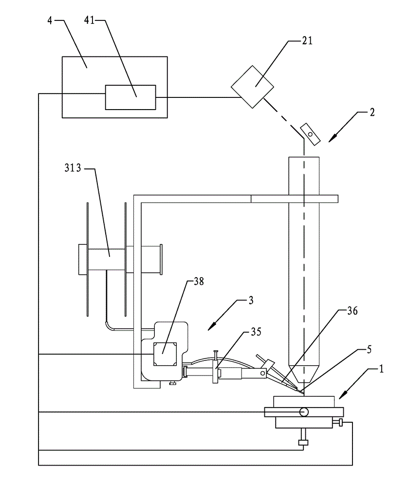
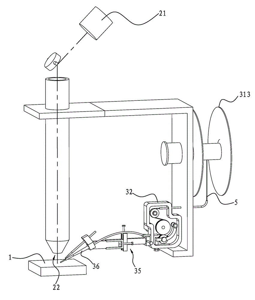
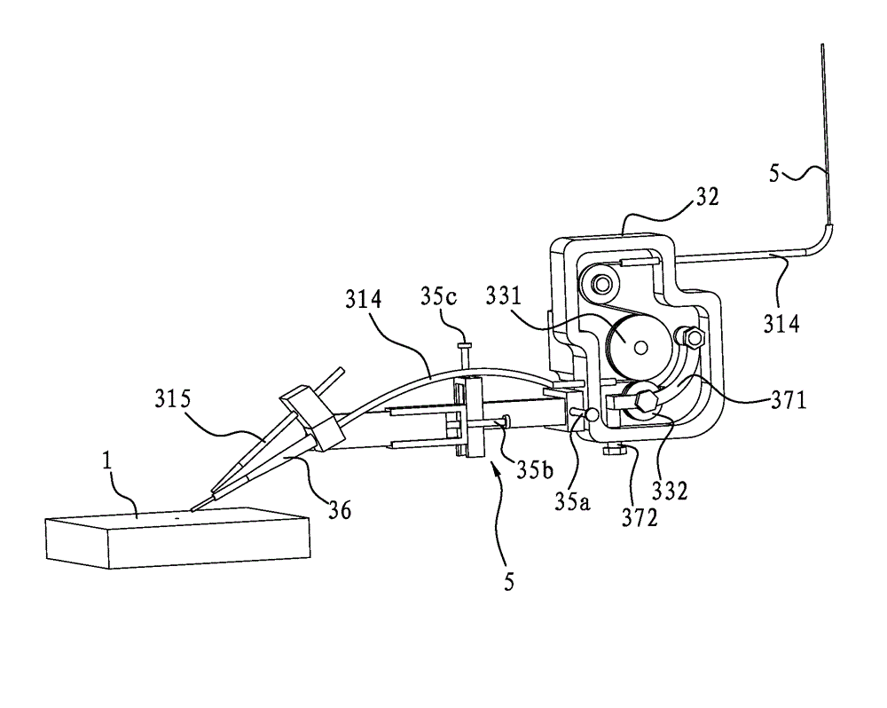

Image

  • Laser cladding forming device and laser cladding forming method of metal part
  • Laser cladding forming device and laser cladding forming method of metal part
  • Laser cladding forming device and laser cladding forming method of metal part

Examples


Embodiment Construction

[0035] Below in conjunction with accompanying drawing, the present invention will be further described, see Figure 1 ~ Figure 4 As shown, a laser cladding molding equipment includes a CNC numerical control work platform, the CNC numerical control work platform is provided with a workbench 1 capable of X-Y-Z three-dimensional movement, a laser device 2 is fixed above the workbench 1, and the The laser beam output end 22 of the laser device 2 faces the workbench 1, which also includes a wire feeding device 3 and a control system 4; the wire feeding device 3 includes a support 32 and a wire feeding nozzle 36, and the support 32 is provided There is a pair of pinch rollers, the driving wheel 331 of the pair of pinch rollers is connected to the output shaft of a stepping motor 38, the stepping motor 38 is fixed on the bracket 32, and the wire feeding nozzle 36 passes through a The three-dimensional adjuster 35 is connected with the support 32; the control system 4 includes a motio...


PUM

PropertyMeasurementUnit
diameteraaaaaaaaaa

Abstract

The invention relates to a laser cladding forming device and a laser cladding forming method of a metal part. The device comprises a work bench in three-dimensional motion, a laser device, a wire feed device and a control system, wherein the wire feed device comprises a pinch roll wheel set, and the drive wheel of the pinch roll wheel set is connected with a stepping motor; the control system comprises a multi-shaft motion control card, and the multi-shaft motion control card is connected with the stepping motor, a work bench driving motor and the laser device respectively. The method comprises the steps of modeling, instruction conversion, sheet forming and deposition forming and the like. Metal wires are molten by laser to form molten drops, the molten drops are piled up and cooled on the work bench, sheets are formed along with the motion of the work bench, and all sheets are deposited layer by layer to form the three-dimensional metal part. The invention has low manufacturing cost, high forming efficiency, high part structure strength, high surface quality and wide application range.

Description

technical field [0001] The invention relates to the technical field of forming and processing of metal parts, in particular to laser cladding forming equipment and a laser cladding forming method of metal parts. Background technique [0002] Traditional metal parts forming methods include CNC machine tool cutting, casting, injection molding and so on. CNC machine tools are commonly used processing and manufacturing equipment. However, it is difficult for CNC machine tools to manufacture parts with complex surfaces or structures, such as thin-walled structures, closed inner cavity structures, and parallel cooling structures; it is also difficult to process parts of certain materials, such as titanium alloys and high-hardness materials. [0003] Rapid prototyping is a new manufacturing method that can solve the problems existing in traditional manufacturing methods. Currently, the most important rapid prototyping materials are: resin, powder, paper, wax, plastic material and...

Claims


Application Information

Patent Timeline
Patent Type & Authority Patents(China)
IPC IPC(8): B22F3/105
Inventor 四库
Owner 北京三帝科技股份有限公司
Learn More