Tray charging method and vibratory tray charger

A charging machine and vibrating technology, applied in the direction of vibrating conveyors, conveyors, conveyor objects, etc., can solve problems such as high cost, large total stroke volume, suction nozzle stability and efficiency improvement, and achieve improved stability Sex, the effect of small total stroke

Inactive Publication Date: 2010-11-17
GRAND TECH SHENZHEN
View PDF5 Cites 48 Cited by
  • Summary
  • Abstract
  • Description
  • Claims
  • Application Information

AI Technical Summary

Problems solved by technology

[0004] The key issue of tray loading is to realize the accuracy and stability of the material grabbing and discharging positions. The key issue of tray loading is to realize the accuracy and stability of the material grabbing and discharging positions. The position of the suction nozzle is fixed, and the discharge position of the suction nozzle changes with

Method used


Image

  • Tray charging method and vibratory tray charger
  • Tray charging method and vibratory tray charger
  • Tray charging method and vibratory tray charger

Examples


Embodiment Construction

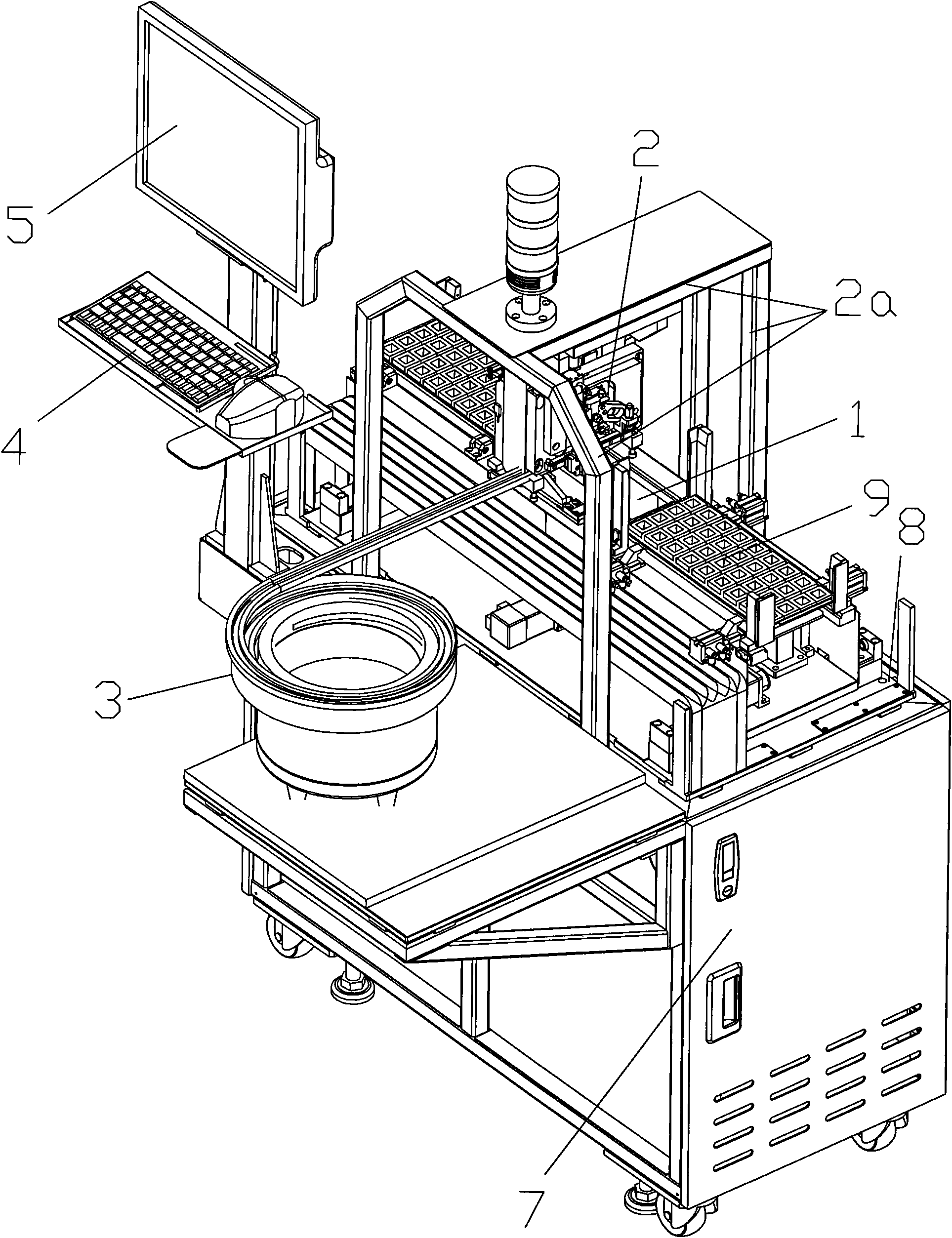
[0042] The vibrating tray loader of the present invention will be further described below in conjunction with the accompanying drawings.

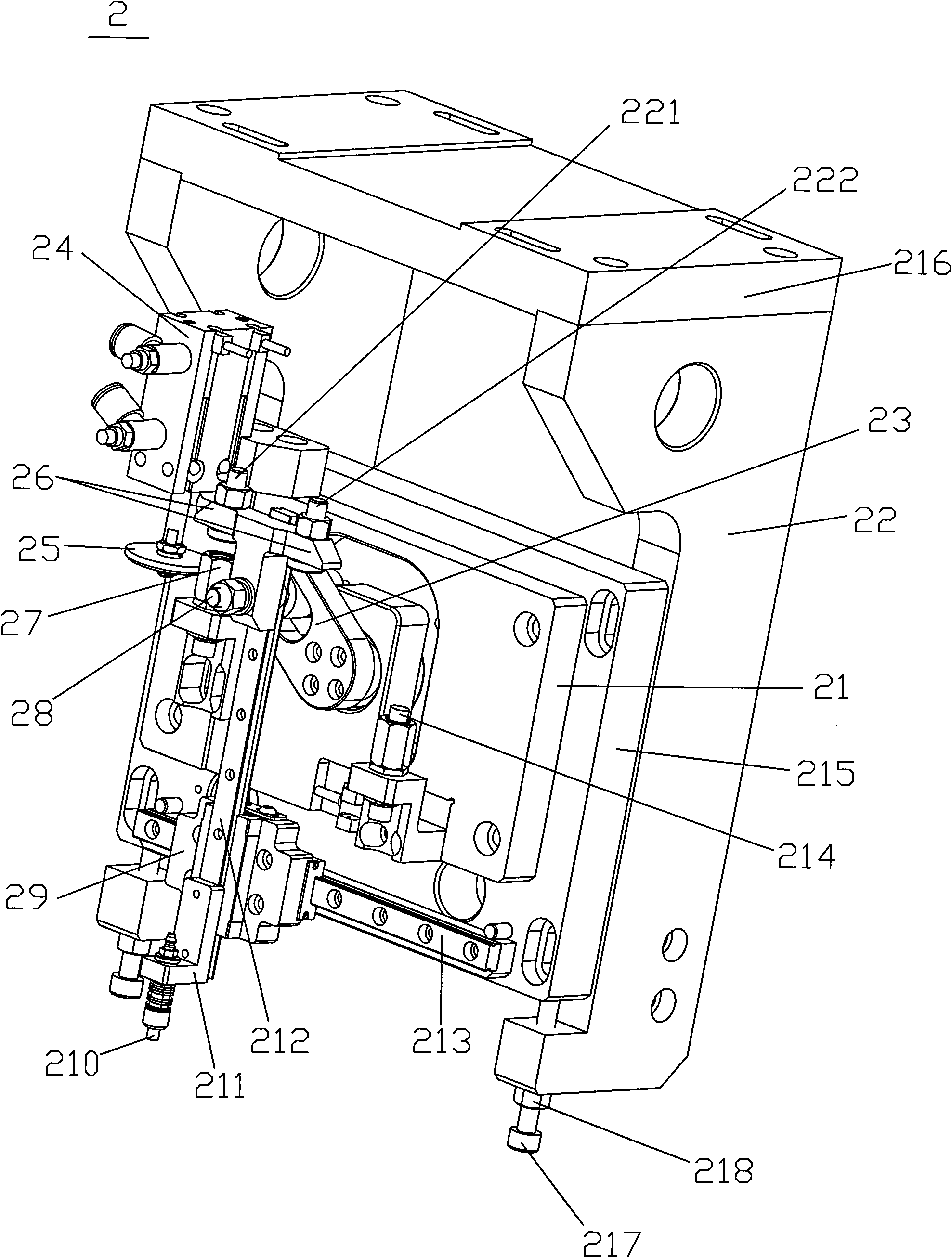
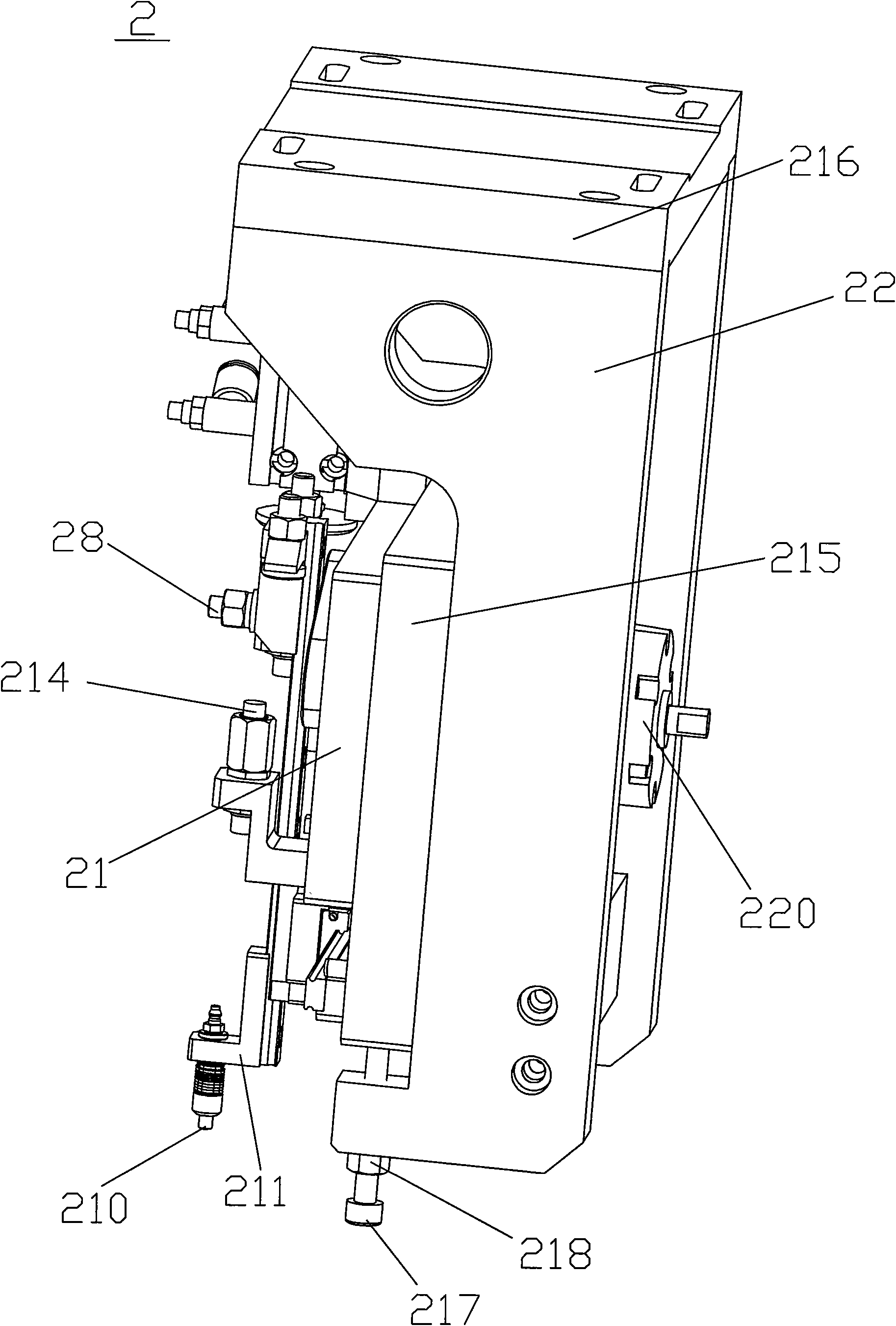
[0043] Such as figure 1 As shown, the vibrating tray loader of the present invention includes a hopper type vibrating device 3, a pick-and-place device 2, a pallet adaptive loading device 1 and an electrical control system 7, wherein the hopper type vibrating device 3 and the pallet automatically The adaptable charging devices 1 are installed on the workbench panel 8, and the grasping and discharging device 2 is installed on the workbench panel 8 through the mounting bracket 2a.

[0044] Such as Figure 7 and 8 As shown, the pallet self-adaptive loading device 1 includes a longitudinal conveying device that drives the pallet to move in the longitudinal direction and a transverse conveying device 15 that drives the longitudinal conveying device to move in a transverse direction perpendicular to the longitudinal direction, and the longitudi...


PUM


Abstract

The invention discloses a tray charging method and a vibratory tray charger. The method comprises that: a hopper type vibrating device conveys integrated circuit blocks in accordance with position and direction requirements to a gripping reference position of a conveying guide rail corresponding to a fixed gripping position one by one; a tray adaptive charging device conveys troughs on a tray to a placing reference position corresponding to a fixed placing position one after another; a suction nozzle of a gripping and placing device reciprocates between the fixed gripping position and the fixed placing position according to a fixed path, and grips the integrated circuit blocks reaching the conveying position of the vibrating device when reaching the gripping position; then, the suction nozzle of the gripping and placing device moves the placing position; and when reaching the placing position, the suction nozzle places the integrated circuit blocks sucked by the suction nozzle into the troughs reaching the conveying position of the charging device. The method can improve the stability of the tray charger under the cooperation of the gripping and placing device and the charging device, and limit the total stroke of the suction nozzle to minimum.

Description

technical field [0001] The invention relates to a tray loading method for integrated circuit blocks and a tray loading device capable of realizing the method. Background technique [0002] The integrated circuit chips produced in batches need to be arranged on the tray according to the front and back sides and the same direction before being sent to the next process for processing, weaved into the braid, or loaded into the material tube. [0003] At present, most of the methods of loading integrated circuit chips into trays rely on cheap labor for tray loading. However, with the shortage of labor market and the increase of labor costs in recent years, as well as the improvement of the quality requirements for tray loading, Many chip manufacturers hope to have a tray loading machine that can replace manual tray loading with low cost, high efficiency and good quality. [0004] The key issue of tray loading is to realize the accuracy and stability of the material grabbing and ...

Claims


Application Information

Patent Timeline
IPC IPC(8): B65G47/91B65G47/74B65G27/00
Inventor 林宜龙田亮张松岭周冠彬林建昌刘国财
Owner GRAND TECH SHENZHEN
Why Eureka
Try Eureka