
Connector of steel tube

A component and round tube technology, applied in temporary or long-term non-important structural fields, can solve problems such as poor safety and labor-intensive

Inactive Publication Date: 2010-11-17
郭倩茹 +1
View PDF0 Cites 9 Cited by
  • Summary
  • Abstract
  • Description
  • Claims
  • Application Information

AI Technical Summary

Problems solved by technology

[0005] Finally, the commonly used scaffolding system has some defects such as poor safety and labor-intensive, which also motivates the search for new connection methods

Method used


Image

  • Connector of steel tube
  • Connector of steel tube
  • Connector of steel tube

Examples


Embodiment Construction

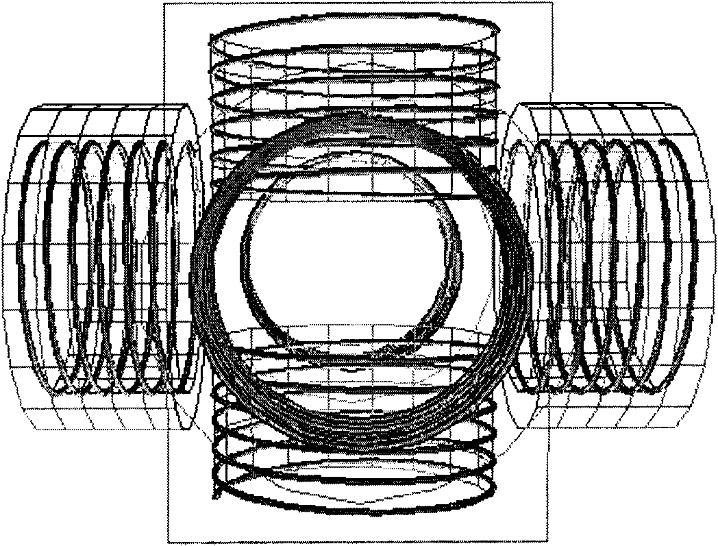
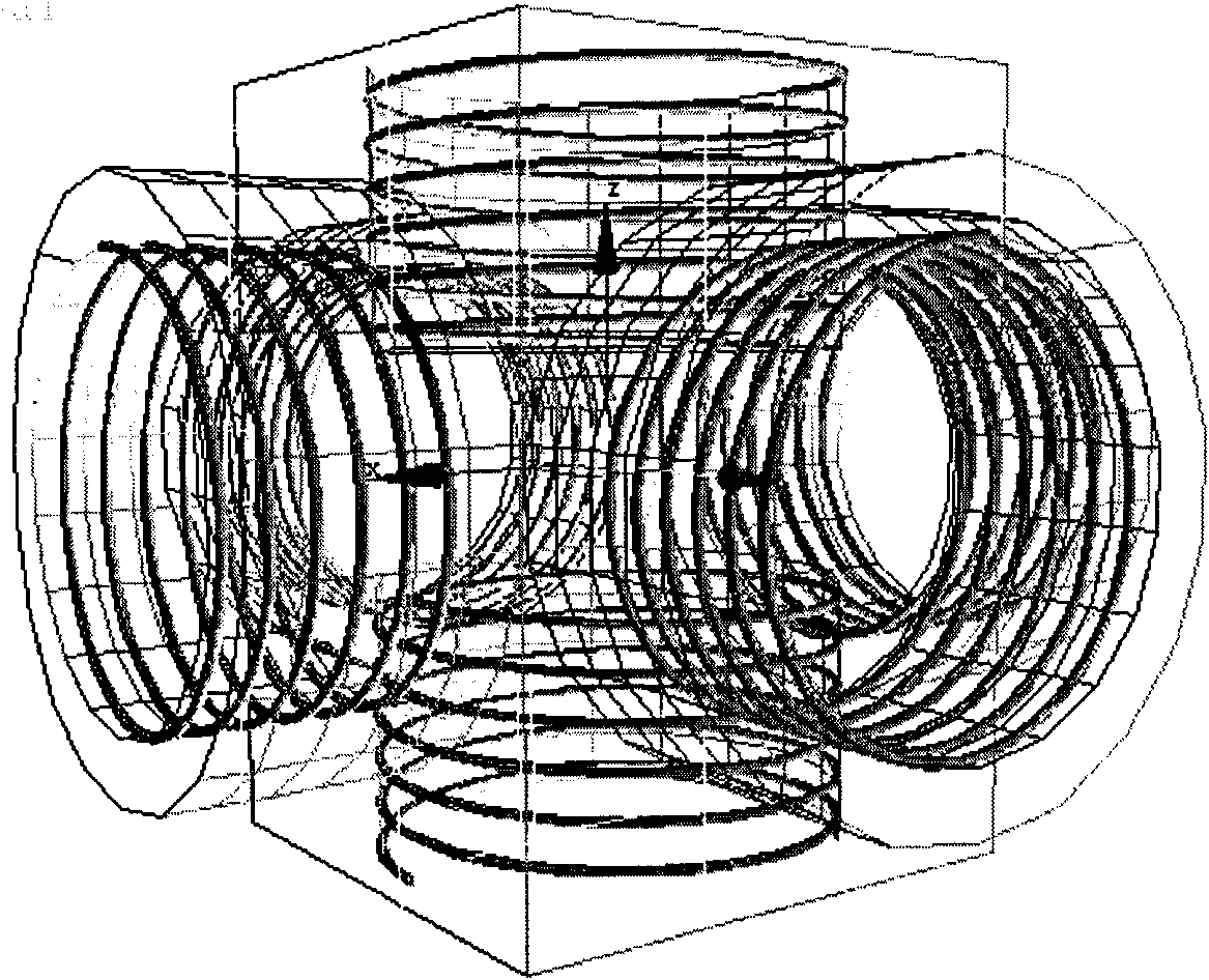
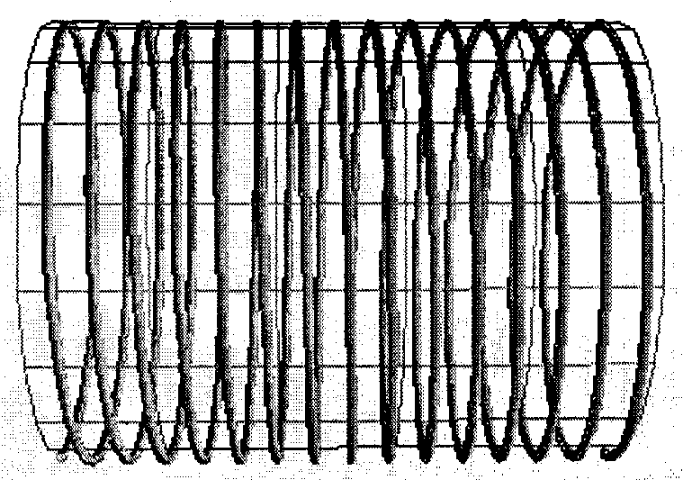
[0016] First, screw the second part, that is, the force transmission screw cylinder, into the third part (the force cylinder)

[0017] Then; hoist the beam into position aligned with the central tube.

[0018] After that, use a wrench to screw the force transmission helical cylinder into the central circular pipe through the two openings at the end of the stressed circular pipe;

[0019] Finally, after the horizontal columns on the first floor are connected, they are screwed into the vertical columns, so that they can be circulated upwards to form a multi-layer structure.


PUM


Abstract

The content of the invention aims at a fast connector of a circular tube, which can safely and fast form a steel frame under the requirement of design specifications. To achieve the above goal, the fast connector comprises the following three parts: a central member, a transmission spiral tube and a circular tube stressing member. The central member is a place where forces from six directions meet and counteract. The transmission spiral tube is an evenly spiral cylinder having a length twice as that of a central spiral cylinder, can freely rotate in a stressing circular tube and the central member and is responsible for connecting the stressing circular tube with the central member and transferring loads. The circular tube stressing member mainly comprises a circular tube beam and a circular tube column, wherein two symmetrical openings are arranged on the openings of the circular tube beam, through which the transmission spiral tube can be easily screwed in the central member by using a spanner so as to achieve connection, protect the transmission spiral tube at the same time and ensure safe and reliable connection.

Description

technical field [0001] The patented technology relates to the field of civil engineering construction, and is suitable for temporary or long-term non-important structures requiring rapid construction. Background technique [0002] Due to its rapid and convenient construction and excellent seismic performance, steel structure has become a structural form that gradually replaces concrete. However, the connection of steel structures has always been a problem that plagues civil engineers. In the traditional three connection methods (riveting, welding, bolts) ), there is an urgent need for some improvements to meet the different requirements of the nature of the project, construction speed, etc. [0003] First of all, in many cases, it is hoped that after the steel is formed into a structure, it can still be used again and form other structural forms after the structure completes its function. This requires the designer to work hard on the connecting parts to make the loading and...

Claims


Application Information

Patent Timeline
IPC IPC(8): E04B1/58E04G7/02
Inventor 郭倩茹崔愉晨
Owner 郭倩茹
Learn More