
Boom system and pumping machinery

A boom and machinery technology, applied in the field of pumping machinery and boom systems, can solve the problems of limited effect of vibration damping technical solutions and inability to reduce concrete pulses, and achieve turbulent flow mitigation, vibration reduction, and speed stability improvement. Effect

Active Publication Date: 2011-09-28
SANY HEAVY IND CO LTD (CN)
View PDF3 Cites 0 Cited by
  • Summary
  • Abstract
  • Description
  • Claims
  • Application Information

AI Technical Summary

Problems solved by technology

The technical solutions disclosed in these patent documents are only from the perspective of controlling the attitude of the boom to contain the amplitude of the vibration at the end of the boom, and cannot reduce the pulse of concrete flow. Therefore, the vibration reduction technical solutions disclosed in the above patent documents have very limited effects

Method used


Image

  • Boom system and pumping machinery
  • Boom system and pumping machinery
  • Boom system and pumping machinery

Examples


Embodiment Construction

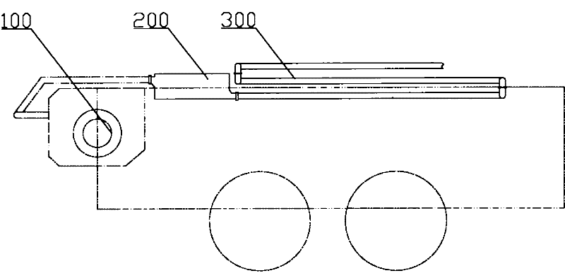
[0026] The present invention will be described in detail below with reference to the accompanying drawings. The description in this part is only exemplary and explanatory, and should not have any limitation on the protection scope of the present invention. The following takes a concrete pump truck as an example to describe the technical solutions provided by the present invention, but the technical solutions provided by the present invention are not limited to being applied to concrete pump trucks, and can also be applied to pumps for conveying ash, mud and other viscous materials. Sending to the machine.

[0027] The basic core of the present invention lies in: reducing the back pressure of the concrete flow field in an appropriate manner at the appropriate position where the concrete flows through, which can effectively improve the turbulence of the concrete flow field, reduce the amplitude of concrete pulsation, and reduce the vibration of the fluid itself. energy. Based on t...


PUM


Abstract

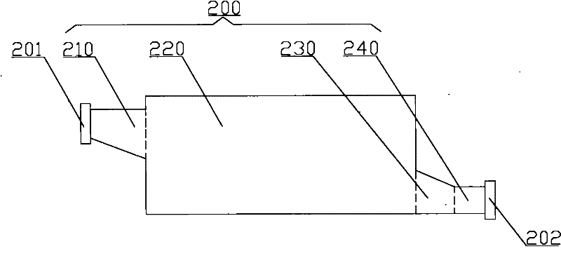
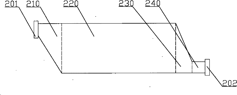
The invention discloses a boom system and pumping machinery provided with the boom system. The boom system comprises a delivery pipe and a vibration damper connected with the delivery pipe; the vibration damper forms a pressure reduction segment and an inlet and an outlet communicated with the pressure reduction segment; and the through-flow section of the pressure reduction segment is larger than that of the inlet and that of the outlet. In the preferential technical scheme, the vibration damper also comprises an expansion segment positioned between the inlet and the pressure reduction segment, and a contracted segment positioned between the pressure reduction segment and the outlet, wherein, the through-flow section of the front end of the expansion segment is smaller than that of the back end thereof; the through-flow section of the front end of the pressure reduction segment is not smaller than that of the back end of the expansion segment; the through-flow section of the front end of the contracted segment is larger than that of the back end thereof; and the through-flow section of the back end of the pressure reduction segment is not smaller than that of the front end of thecontracted segment. In the boom system, the pressure reduction segment of the vibration damper can reduce the pulsation amplitude of fluid, thus further reducing vibration of the boom system caused by fluid pulsation.

Description

Technical field [0001] The invention relates to a technology for pumping viscous fluids such as concrete, in particular to a boom system, and also to a pumping machine with the boom system. Background technique [0002] The concrete pump truck is currently one of the widely used concrete machinery. The concrete pump truck generally includes a pumping device and a boom system. The pumping device generally includes a hopper, a conveying cylinder, and a distribution valve. The hopper is used to store concrete. The distribution valve can be driven by a swing cylinder to switch states and form the output port of the pumping device. The boom system includes a boom and a conveying pipe. The boom includes a joint arm formed by multiple sections that are sequentially hinged and connected by a transverse hinge shaft. The conveying pipe includes multiple pipes connected in sequence, and the pipes are respectively fixed on the corresponding joint arms; the conveying pipe It has an input po...

Claims


Application Information

Patent Timeline
Patent Type & Authority Patents(China)
IPC IPC(8): E04G21/02F16L55/02
Inventor 易小刚周翔喻志平
Owner SANY HEAVY IND CO LTD (CN)
Learn More