
Ventilation system and controlling method of the same

A ventilation system and control method technology, applied in the field of ventilation systems, can solve problems such as damage to heat exchangers, and achieve optimal ventilation effects

Inactive Publication Date: 2013-05-22
LG ELECTRONICS INC
View PDF5 Cites 0 Cited by
  • Summary
  • Abstract
  • Description
  • Claims
  • Application Information

AI Technical Summary

Problems solved by technology

[0008] That is, when the outside air temperature is below zero, the heat exchanger, etc. may be damaged by freezing of the outside cold air

Method used


Image

  • Ventilation system and controlling method of the same
  • Ventilation system and controlling method of the same
  • Ventilation system and controlling method of the same

Examples


Embodiment Construction

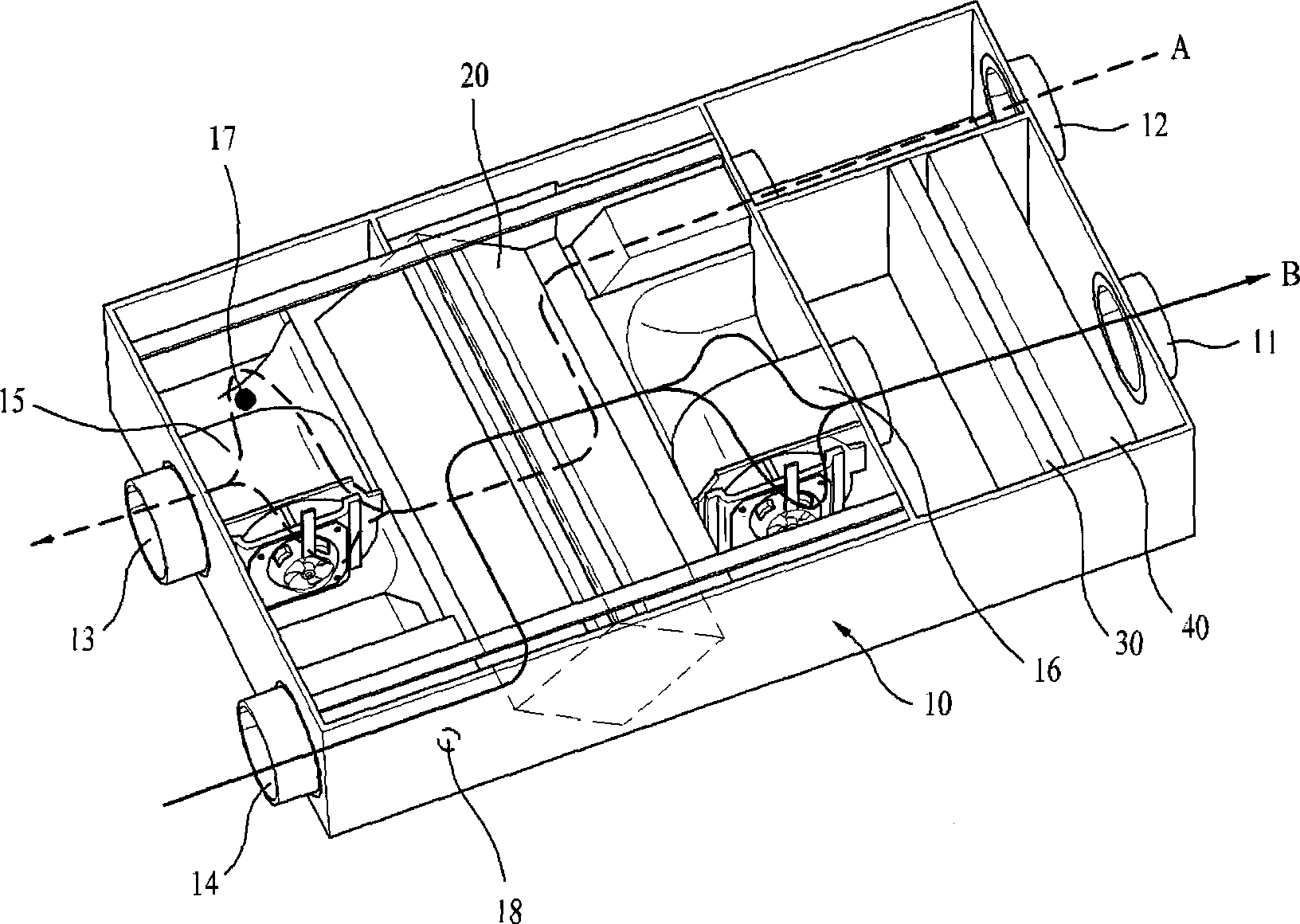
[0038] Hereinafter, preferred embodiments of the present invention will be described in detail with reference to the accompanying drawings. However, the present invention is not limited to the embodiments described here, and may be implemented in other forms. The embodiments introduced here are only provided to make the disclosed content more complete and fully convey the idea of ​​the present invention to those skilled in the art. The same reference numerals denote the same constituent elements throughout the specification. figure 1 One embodiment of the ventilation system according to the present invention is shown.

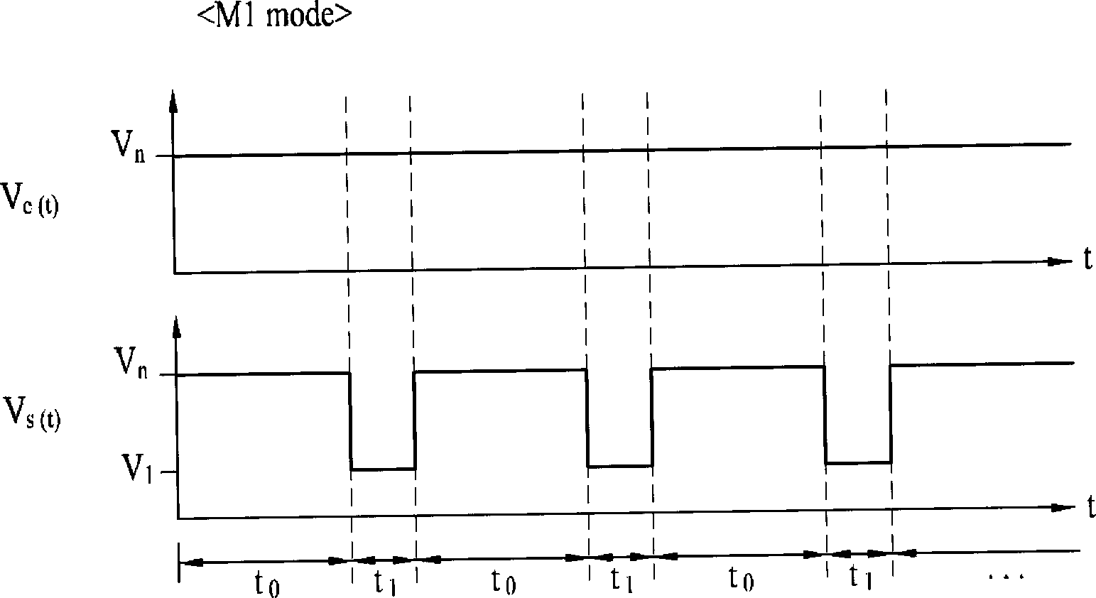
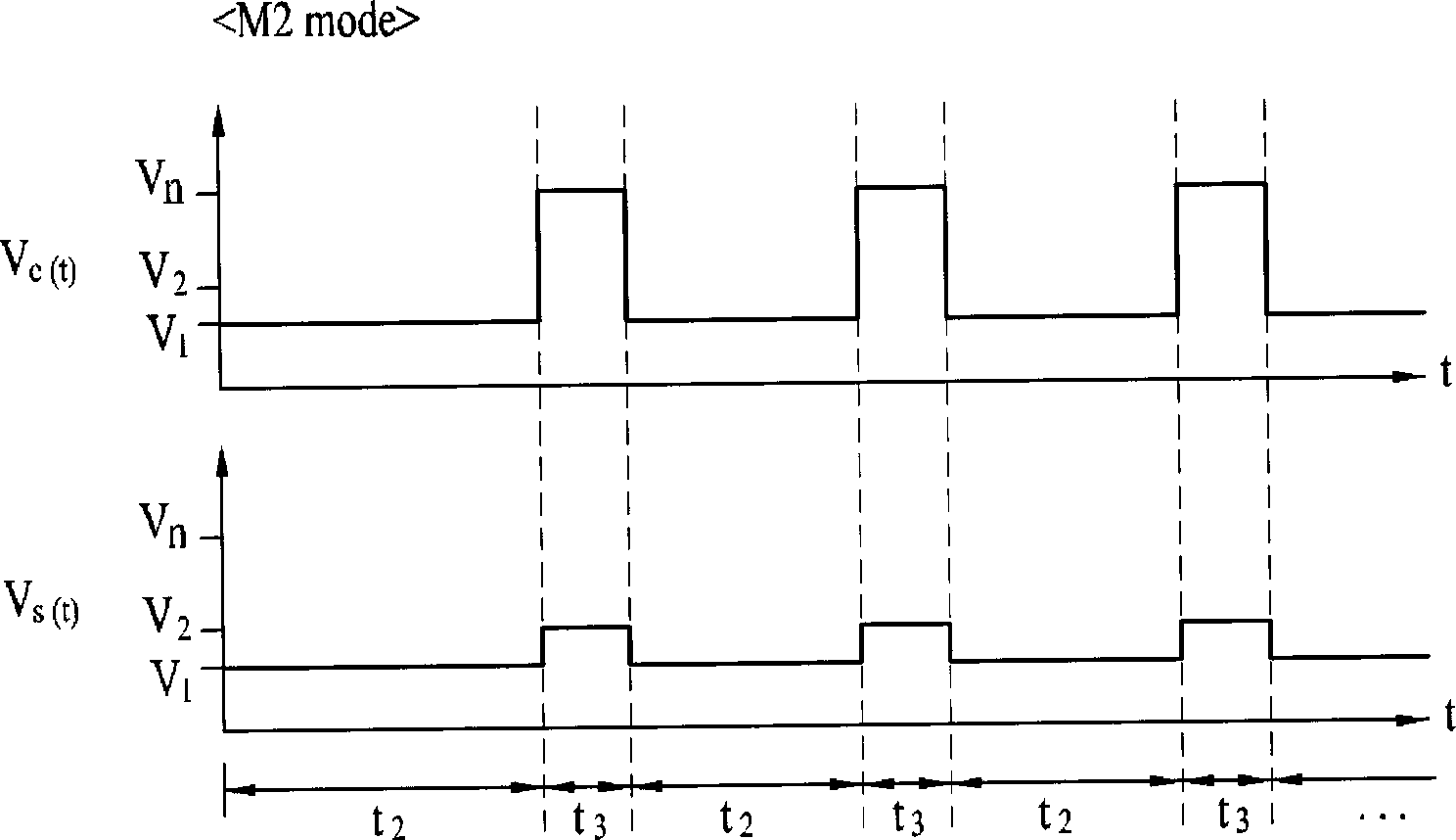
[0039] in addition, figure 2 The operating modes of the air supply fan 16 and the exhaust fan 15 in the first operation mode are shown. image 3 and Figure 4 The operation modes of the air supply fan 16 and the exhaust fan 15 in the second operation mode are shown in respective examples.

[0040] figure 1 The illustrated ventilation system includes: a h...


PUM


Abstract

A ventilation system and a controlling method of such a ventilation system are provided. The ventilation system may exhaust internal air from and draw fresh external air into a designated space. When an outdoor temperature is below a freezing point, some of the internal components of the ventilation system may be damaged due to the low external air temperature. This ventilation system controls operation of a supply fan and / or an exhaust fan based on the temperature of supplied and / or exhausted air to prevent such damage.

Description

technical field [0001] The invention relates to a ventilation system. Due to the respiration of living organisms, the carbon dioxide content of the air in a closed space increases over time, which affects the respiration of living organisms. Therefore, when many people stay in a small space such as offices or vehicles, it is necessary to replace indoor polluted air with outdoor fresh air at any time. At this time, a ventilation system needs to be used. Background technique [0002] In the prior art, only the indoor air is forcibly exhausted to the outside by a single blower. However, in the case where only indoor air is forcibly exhausted by a single blower, cold or hot air in the room is directly discharged to the outside, which is not conducive to energy saving. [0003] In the case of using only one blower, the supply of outside air to the room is performed through a window or a gap in the door or the like. [0004] In this case, since the outside air whose temperatur...

Claims


Application Information

Patent Timeline
Patent Type & Authority Patents(China)
IPC IPC(8): F24F7/013F24F11/00
CPCY02B30/16F24F2011/0064F24F11/04F24F11/0079Y02B30/746F24F12/006F24F11/0012Y02B30/563F24F11/30F24F2110/10F24F11/65F24F11/77F24F11/74Y02B30/56Y02B30/70F24F11/76F24F11/46F24F11/0001Y02B30/00
Inventor 赵敏喆宋在宣金正勋
Owner LG ELECTRONICS INC
Learn More