Torque measurement device and method

A technology of torque measurement and measurement point, which is applied in the field of torque change measurement devices for detecting rotating machinery during operation, can solve the problems of high installation requirements, large measurement errors and high environmental requirements of photoelectric torque sensors, saving measurement preparation time, The effect of low human influence and high measurement accuracy

Inactive Publication Date: 2010-11-17
BAOSHAN IRON & STEEL CO LTD
View PDF2 Cites 25 Cited by
  • Summary
  • Abstract
  • Description
  • Claims
  • Application Information

AI Technical Summary

Problems solved by technology

[0007] The technical problem to be solved by the present invention is to provide a torque measuring device and method to solve the defects in the prior art that the clamp ring type torque sensor has a complex structure and large measurement error; the photoelectric torque sensor has high installation requirements and high environmental requirements

Method used


Image

  • Torque measurement device and method
  • Torque measurement device and method
  • Torque measurement device and method

Examples


Embodiment 1

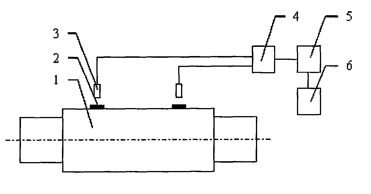
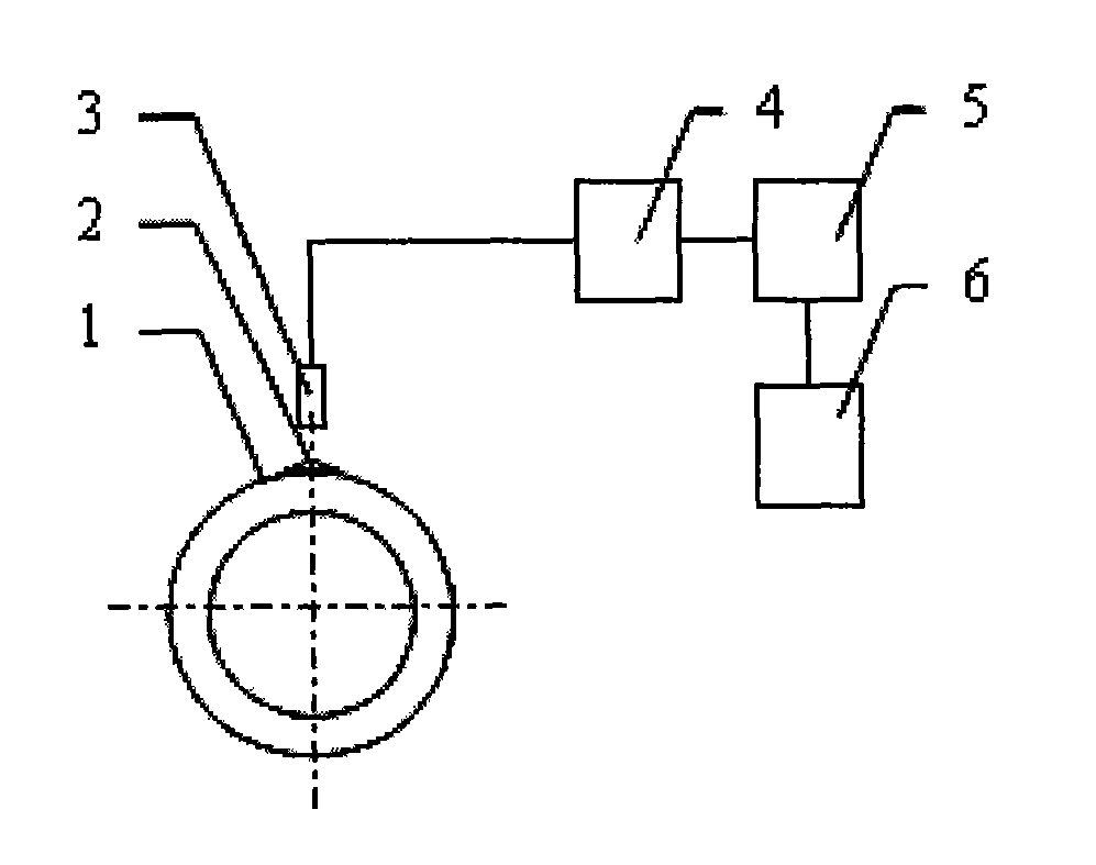
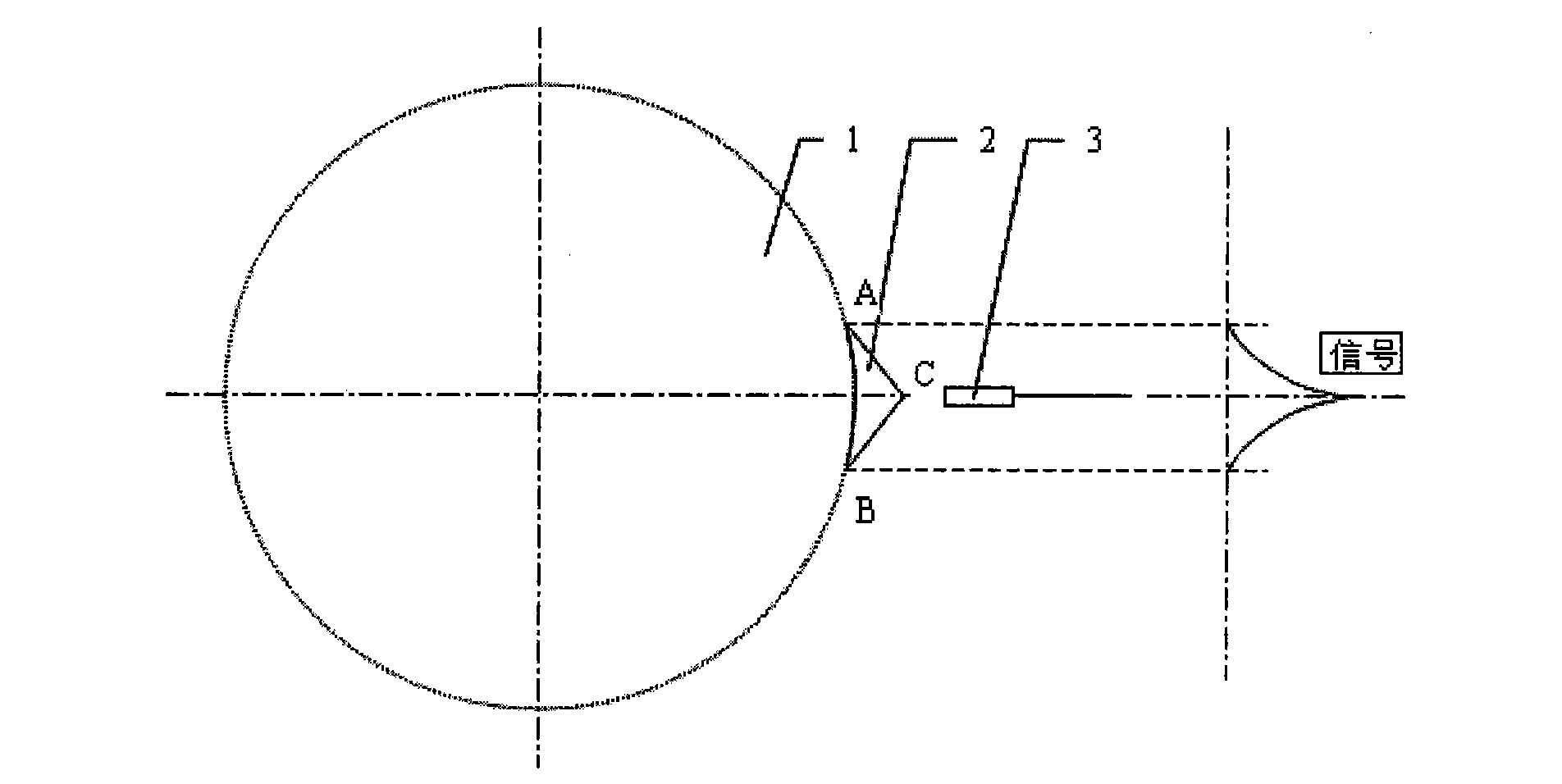
[0031] see figure 1 , 2 As shown, a torque measuring device includes a soft magnet 2, an inductive sensor 3, a signal conditioning module 4, an acquisition module 5 and a computer processing system 6. There are two soft magnets 2, which are respectively arranged on the measured axis 1 On any two measurement points on the circumferential surface, the two measurement points are separated by a certain distance L in the axial direction, and one inductive sensor 3 is fixed to the soft magnetic body 2, and the two inductive sensors 3 pass through the signal conditioning module 4 and the acquisition module 5 synchronously The collected signal is transmitted to the computer processing system 6; the soft magnetic body 2 is a triangular prism whose cross section becomes an isosceles triangle, and the measurement using the device comprises the following steps:

[0032] 1) Select two measuring points, and arbitrarily set two measuring points separated by a certain axial distance on the c...

Embodiment 2

[0061] A torque measuring device, comprising a hard magnet 2, an inductive sensor 3, a signal conditioning module 4, an acquisition module 5 and a computer processing system 6, wherein there are two hard magnets 2, which are respectively arranged on any surface of the circumference of the measured shaft 1 On the two measurement points, the axial distance of the two measurement points is a certain distance L, and an inductive sensor 3 is fixed to the hard magnet 2, and the two inductive sensors 3 are synchronously collected by the signal conditioning module 4 and the acquisition module 5. The signal is transmitted to the computer processing system 6; the hard magnet 2 is a cone, so the apex of the cone is selected as a reference point, which can improve the measurement accuracy.

Embodiment 3

[0063] A torque measuring device, comprising a hard magnet 2, an inductive sensor 3, a signal conditioning module 4, an acquisition module 5 and a computer processing system 6, wherein there are two hard magnets 2, which are respectively arranged on any surface of the circumference of the measured shaft 1 On the two measurement points, the axial distance of the two measurement points is a certain distance L, and an inductive sensor 3 is fixed to the hard magnet 2, and the two inductive sensors 3 are synchronously collected by the signal conditioning module 4 and the acquisition module 5. The signal is transmitted to the computer processing system 6; the hard magnet 2 is a cylinder, and the endpoints on both sides of the cylinder are selected as reference points.


PUM


Abstract

The invention belongs to the technical field of rotating machinery detection and in particular relates to a torque change measurement device and method for detecting the rotating machinery in the operation process. The torque measurement device comprises magnets (2), inductive transducers (3), a signal conditioning module (4), an acquisition module (5) and a computer processing system (6). The torque measurement method comprises the following steps: 1) selecting two measuring points; 2) installing the torque measurement device; 3) acquiring an unloaded initial signal; 4) acquiring a loaded turn signal; and 5) computing the torque of the shaft to be measured. The invention is convenient and simple to install, easy and practical to operate and high in measurement precision, has no requirement for installation precision, basically dispenses with adjustment, can greatly save the measurement preparation time, simultaneously has low requirement for the linearity of the sensor, saves cost and can be widely applied to the field of rotating machinery monitoring and diagnosis.

Description

technical field [0001] The invention belongs to the technical field of rotating machinery detection, and in particular relates to a torque change measuring device and method for detecting rotating machinery during operation. Background technique [0002] At present, the status monitoring of equipment in the production process has become a trend, especially the continuous production equipment of iron and steel enterprises has huge losses due to sudden accidents. As the contradiction between the upgrading of iron and steel products and the aging of equipment becomes more and more prominent, it is even more necessary to monitor its operation. [0003] Existing rotating machines generally include motors, rotating shafts, couplings, gearboxes, loads, etc. Torque transmission is performed between the various parts of the rotating machines, thereby closely linking them together. During the operation of rotating machinery, due to changes in the state of the equipment itself and chan...

Claims


Application Information

Patent Timeline
Patent Type & Authority Applications(China)
IPC IPC(8): G01L3/00
Inventor 王泽济王瑞庭李山青
Owner BAOSHAN IRON & STEEL CO LTD
Why Eureka
Try Eureka