
Optical transceiver module and system and optical transceiving method

An optical transceiver module, optical transceiver technology, applied in transmission systems, electromagnetic transceivers, electromagnetic wave transmission systems, etc., to achieve the effect of reducing the number of pins

Active Publication Date: 2010-11-17
VIA TECH INC
View PDF8 Cites 12 Cited by
  • Summary
  • Abstract
  • Description
  • Claims
  • Application Information

AI Technical Summary

Problems solved by technology

However, when the optical transceiver module of the prior art is directly connected to the existing electronic transceiver with common interface specifications, the electronic transceiver will enter the disable mode (disable mode). Therefore, the present invention proposes a new optical transceiver module, system and optical transceiver. Sending and receiving method to solve the problems existing in the prior art

Method used


Image

  • Optical transceiver module and system and optical transceiving method
  • Optical transceiver module and system and optical transceiving method
  • Optical transceiver module and system and optical transceiving method

Examples


Embodiment Construction

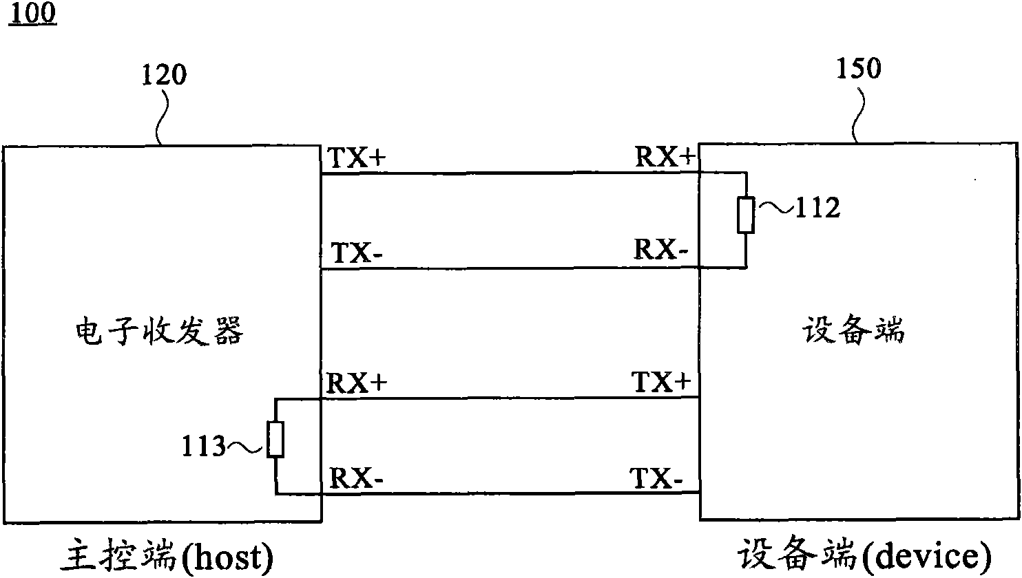
[0020] figure 1 is a block diagram of a prior art electronic transceiver system 100 . The electronic transceiver 120 can be a high-speed electronic transceiver that supports hot-swap function, such as Peripheral Component Interconnect Express (PCIE) interface specification or Universal Serial Bus Version 3.0 (USB3.0) interface specification. When the electronic transceiver 120 is used as the main control terminal (host) of the transmission system, it will poll (polling) whether there is a device end (device) inserted at regular intervals. When the device end 150 is detected, the electronic transceiver The 120 initiates the transmission of a link training sequence to establish a link with the device 150 . Of course, the device side 150 will also poll whether the main control terminal exists at regular intervals, and when detecting the existence of the electronic transceiver 120 as the main control terminal, it will also initiate the transmission of a link training sequence to ...


PUM


Abstract

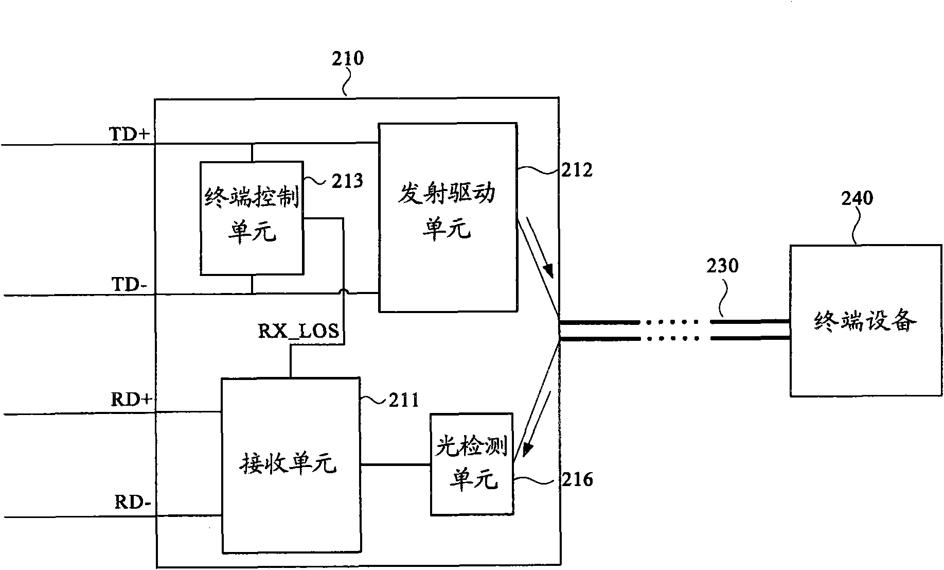
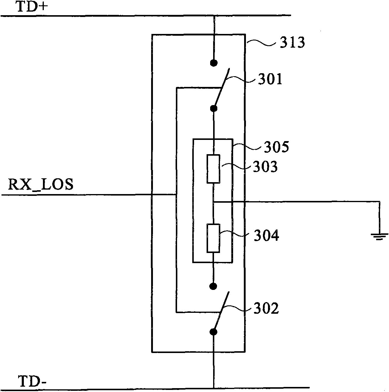
The invention discloses optical transceiver module and system and an optical transceiving method, wherein the optical transceiver module comprises a receiving unit, a launching drive unit and a terminal control unit, wherein the receiving unit is used for outputting lost signals of a receiving terminal, the launching drive unit comprises a positive receiving signal port and a negative receiving signal port, and the terminal control unit is coupled between the positive receiving signal port and the negative receiving signal port. Whether a difference terminal impedance is accessed and coupled between the positive receiving signal port and the negative receiving signal port or not is controlled according to the lost signals of the receiving terminal.

Description

technical field [0001] The invention relates to an optical transceiver module and system and an optical transceiver method, in particular to an optical transceiver module system and an optical transceiver method capable of accurately detecting terminal equipment. Background technique [0002] With the development of optical transmission technology, the advantages of optical fiber transmission in transmission rate / transmission distance and anti-interference ability have made optical transceiver modules (optical transceiver modules) more and more widely used. Due to the advantages of optical transmission technology, more and more applications now hope that optical transceiver modules can be connected to existing electronic transceivers, making traditional interfaces such as Peripheral Component Interconnect Express (PCIE) interface specification or Universal Serial Bus Electronic transceivers with version 3.0 (USB3.0) interface specifications can also perform optical fiber com...

Claims


Application Information

Patent Timeline
Patent Type & Authority Applications(China)
IPC IPC(8): G02B6/42H04B10/24
CPCH04B10/40
Inventor 汤金宽赖瑾
Owner VIA TECH INC
Learn More