Full-automatic hydraulic plate pulling mechanism of filter press

A filter press, fully automatic technology, applied in the direction of filtration separation, separation methods, chemical instruments and methods, etc., can solve the problems that the filter plate cannot be automatically and stably pulled apart, the labor intensity is high, the motor starting current is large, etc., and the artificial Low labor intensity, high drawing efficiency and stable operation

Inactive Publication Date: 2010-11-24
江苏苏东化工机械有限公司
View PDF6 Cites 10 Cited by
  • Summary
  • Abstract
  • Description
  • Claims
  • Application Information

AI Technical Summary

Problems solved by technology

[0003] In order to solve the problems in the prior art that the filter press has a large instantaneous pulling force when pulling the filter plate, a large starting current of the motor, which is easily burnt out due to overcurrent, a short service life, and the filter plate cannot be pulled apart automatically and stably, high labor intensity and high use cost. , the object of the present invention is to provide a fully automatic hydraulic plate pulling mechanism for a filter press with simple structure, low energy consumption, stable pulling of the filter plate, high efficiency, low labor intensity, low use cost and long service life

Method used


Image

  • Full-automatic hydraulic plate pulling mechanism of filter press
  • Full-automatic hydraulic plate pulling mechanism of filter press
  • Full-automatic hydraulic plate pulling mechanism of filter press

Examples


Embodiment Construction

[0012] The present invention will be further described below in conjunction with drawings and embodiments.

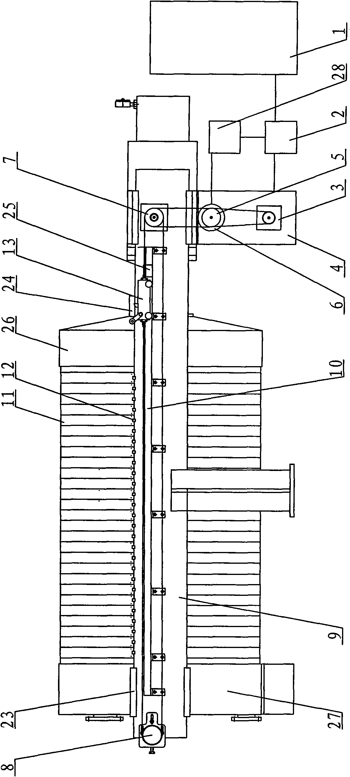
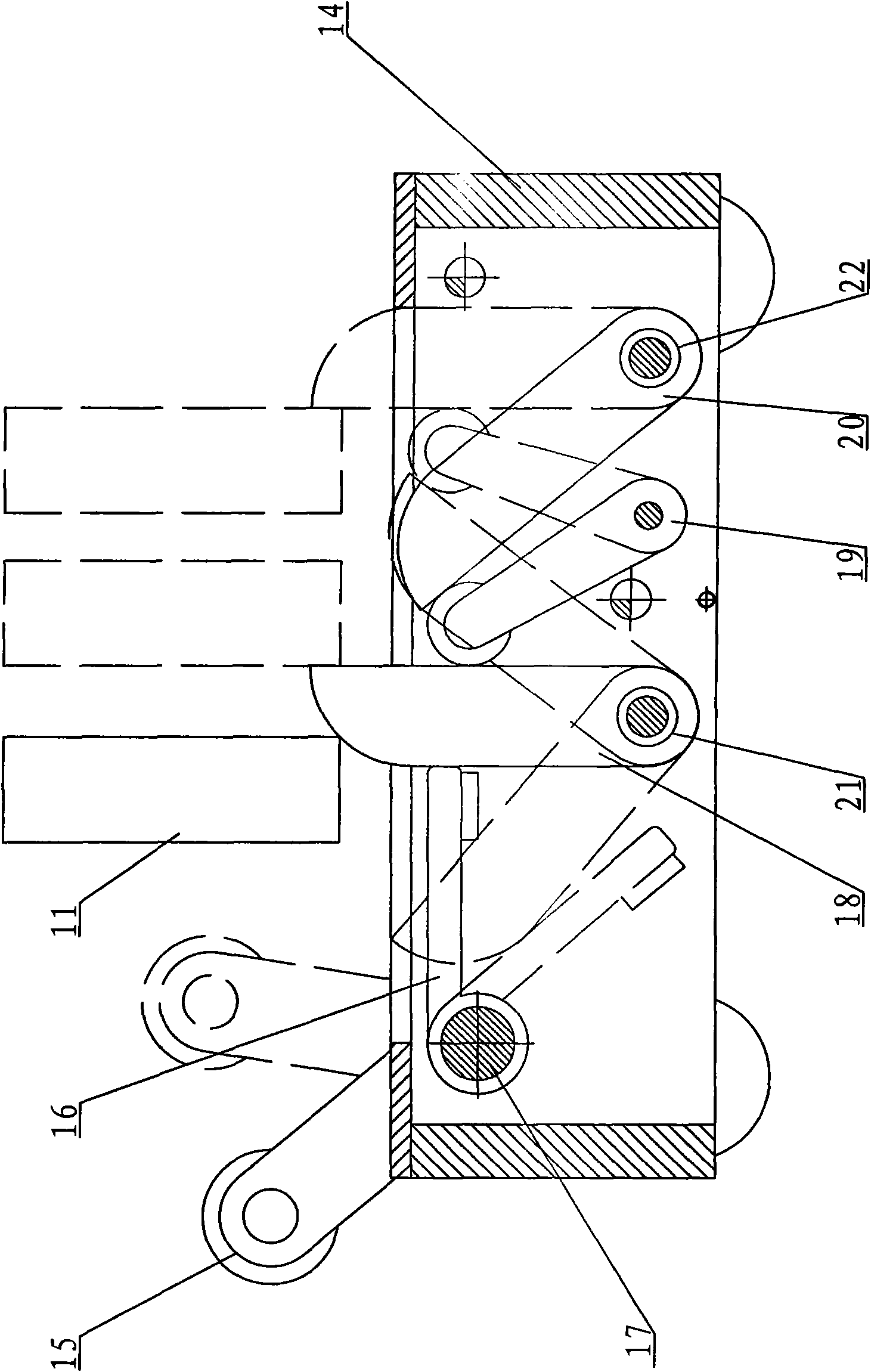
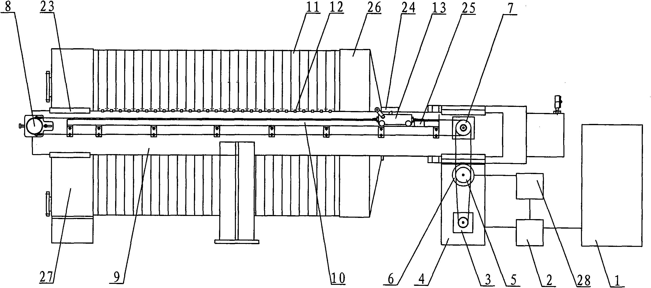
[0013] figure 1 As shown, the fully automatic hydraulic plate pulling mechanism of the filter press includes a main beam 9 , a filter plate group 11 , a plate pulling device 13 , an oil motor 3 and a hydraulic station 1 . The two ends of the main beam 9 are respectively supported on the fixed end support 27 and the oil cylinder assembly support 4, the movable platen 26 is slidably supported on the main beam 9, and a filter plate group is arranged between the movable platen and the fixed end support. Each filter plate 11 is slidably supported on the main beam 9 through the hanging lugs 12 on both sides of the filter plate. The main beam 9 is provided with a track 10, and the track at the end of the fixed end bracket 27 is provided with a reset block 23. The track at the end is provided with a reset block 24 and a travel switch 25; the lower part of the oil cylinder asse...


PUM


Abstract

The invention relates to a full-automatic hydraulic plate pulling mechanism of a filter press. The full-automatic hydraulic plate pulling mechanism comprises filter press main beams, a filter plate group, a cylinder assembly bracket, a plate pulling device and a PLC control system, wherein the outer side of the main beam between the fixed end and the compressed end of the filter press is provided with a track; the main beams at the fixed end and the compressed end of the filter press are respectively provided with a driven wheel and a resetting check block; the plate pulling device is connected in the track through a chain on the driven wheel; the cylinder assembly bracket at the compressed end of the filter press is provided with a driving wheel, an oil motor and a proximity sensor; the oil motor is connected with a hydraulic station through an electromagnetic directional valve; and the proximity sensor is connected with the PLC control system. In the invention, the plate pulling device is adopted to be contacted with filter plates of the filter plate group so as to provide resistance information for the proximity sensor, and then the proximity sensor utilizes the PLC control system to control the electromagnetic directional valve to provide hydraulic power for the oil motor, thus realizing that the plate pulling device pulls the filter plates by reversing; and the full-automatic hydraulic plate pulling mechanism has compact integral structure, stable operation, long service life, high efficiency, no need of manual auxiliary operation, lower labor intensity and high automaticity, and the plate pulling device can smoothly and steadily pull the filter plates by reversing.

Description

technical field [0001] The invention relates to a plate pulling mechanism of a filter press, in particular to a fully automatic, hydraulically driven plate pulling mechanism of a filter press. Background technique [0002] The existing automatic plate pulling method of the filter press adopts the mechanical pendulum plate type and the frequency conversion variable speed method. The disadvantage is that the starting current is large when the mechanical pendulum plate type and the electric frequency conversion variable speed method are used to pull the filter plate, and the chain and sprocket slippery phenomenon is prone to occur during the process of pulling the filter plate. , the puller handles on both sides are not easy to synchronize, the instantaneous pull force is too large, the motor is burnt out due to overcurrent, the filter plate lugs are easily deformed, the cost is high, and the service life is short; and there are slippage phenomena on both sides of the puller han...

Claims


Application Information

Patent Timeline
Patent Type & Authority Applications(China)
IPC IPC(8): B01D25/172
Inventor 汪统华陈怀兵汪立虎
Owner 江苏苏东化工机械有限公司
Why Eureka
Try Eureka