Electric automobile power battery quick-change mechanism

A technology for power batteries and electric vehicles. It is applied in the direction of electric power devices, power devices, and battery pack components. It can solve the problems of time-consuming, cumbersome procedures, and heavy workload for battery disassembly and replacement, and achieve easy and labor-saving pick-and-place processes. , The effect of saving time and effort and improving production efficiency

Inactive Publication Date: 2010-11-24
纽贝耳文化创意(杭州)有限公司
View PDF8 Cites 49 Cited by
  • Summary
  • Abstract
  • Description
  • Claims
  • Application Information

AI Technical Summary

Problems solved by technology

[0004] The present invention mainly provides an electric vehicle power battery quick-change mechanism with simple structure, time-saving and labor-saving operation, and convenient and fast battery replacement, which solves the time-consuming, laborious, cumbersome process and low efficiency of battery disassembly and replacement existing in the prior art , heavy workload and other technical issues

Method used


Image

  • Electric automobile power battery quick-change mechanism
  • Electric automobile power battery quick-change mechanism
  • Electric automobile power battery quick-change mechanism

Examples


Embodiment 1

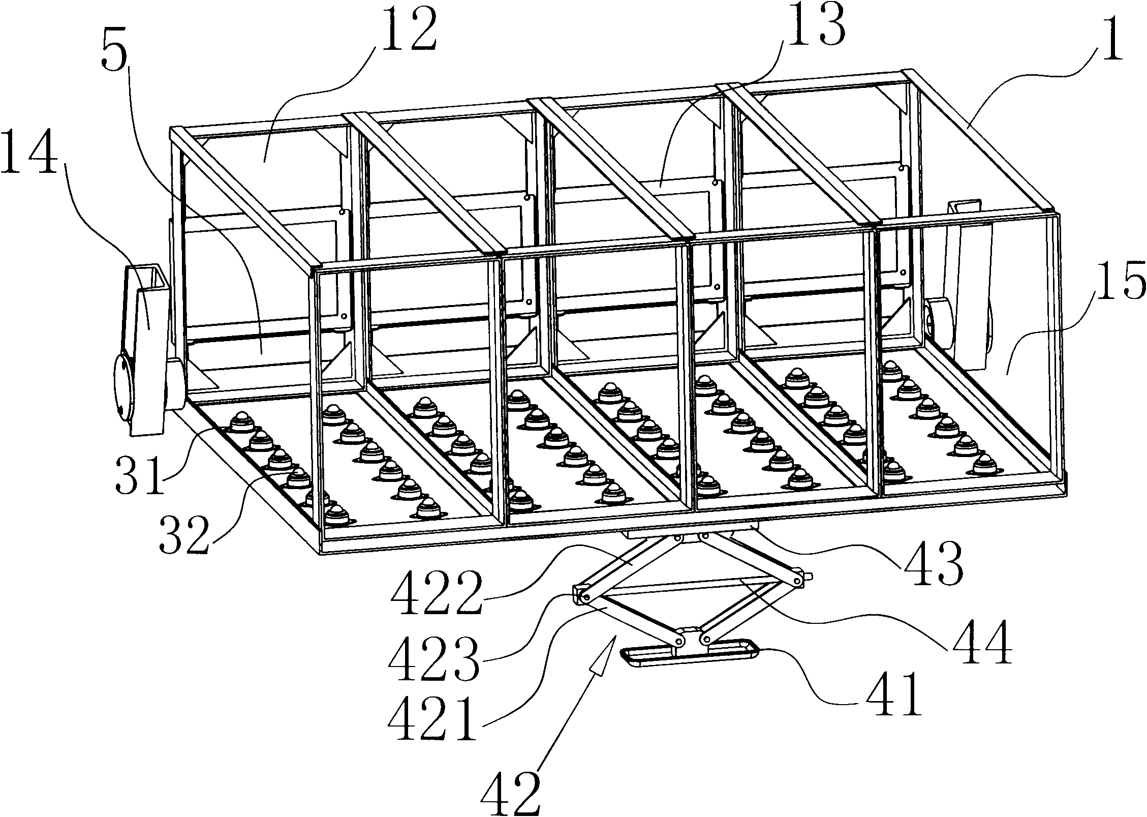
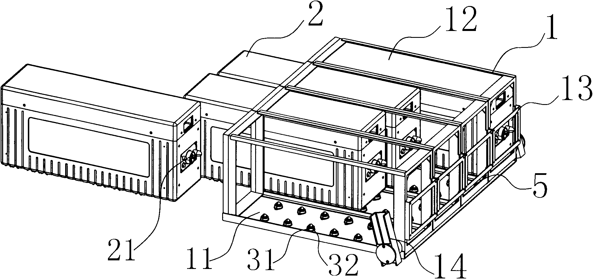
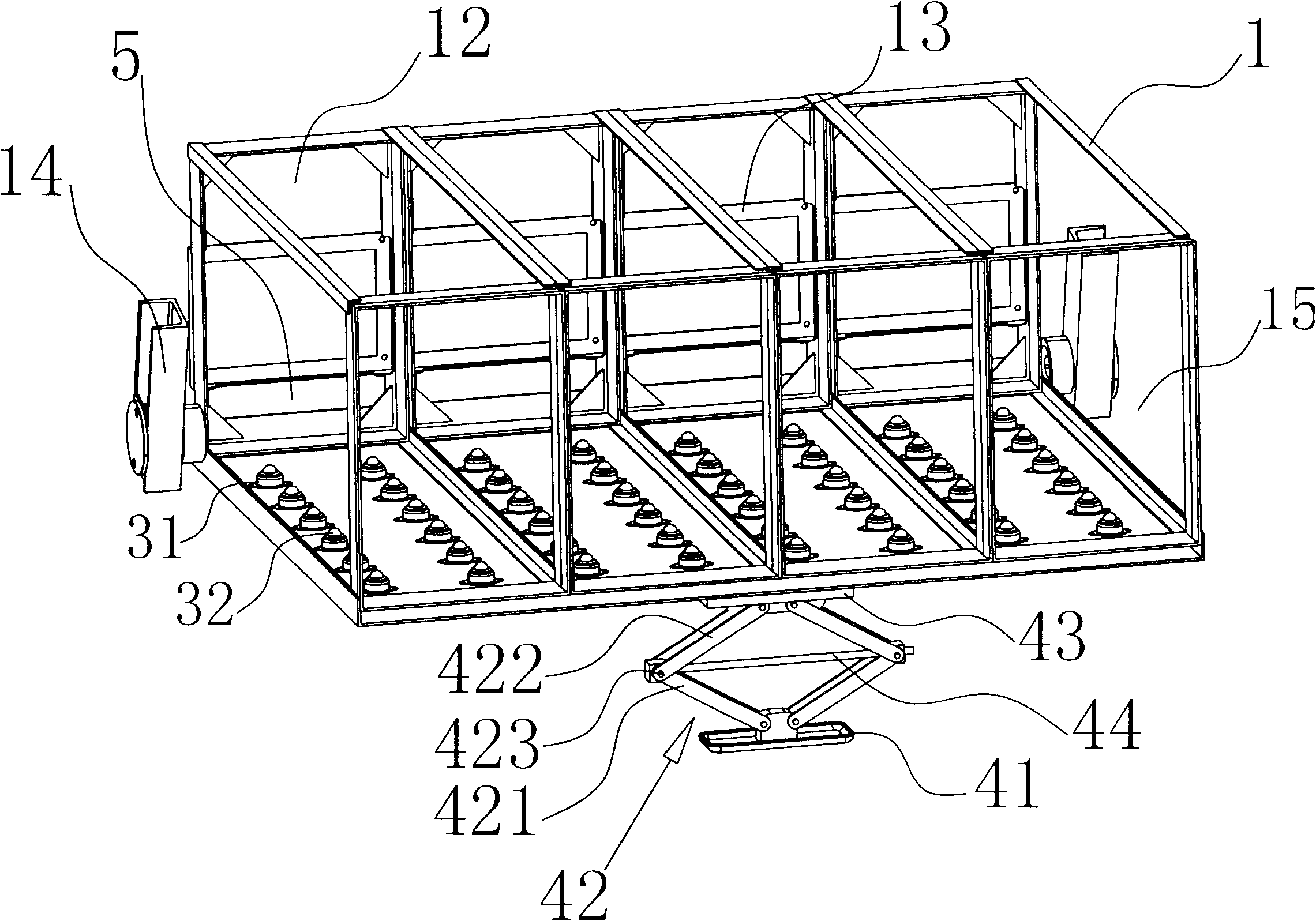
[0020] like figure 2As shown, in the electric vehicle power battery quick-change mechanism of the present invention, in order to save cost and reduce weight, the battery installation frame 1 in the electric vehicle power battery sliding assembly mechanism of the present invention is welded by square tube profiles, which includes rectangular battery The installation frame 1 and the battery pack 2 installed in the battery installation frame 1 are pivotally connected to the side of the long side of the battery installation frame 1 through the horizontal connecting shaft 5 in the sinking groove of the automobile chassis, and on the side corresponding to the short side of the battery installation frame 1 A pair of connection plates 14 are symmetrically welded on the top, and the two ends of the horizontal connection shaft 5 pass through the connection plate 14 and are welded symmetrically on the connection plate 14. On the battery installation frame 1, four parallel partitions are ...

Embodiment 2

[0023] The lifting mechanism is a vertical screw rod and a vertical screw nut screwed on the vertical screw rod. The nut is welded and fixed on the chassis of the car, and the lower end of the vertical screw rod is connected with a geared motor through a coupling. The sliding mechanism includes a pair of slide rail grooves on the inner bottom plate 11 corresponding to the positioning groove 12 and a pair of sliders on the bottom surface of the battery pack 2 that match with the slide rail grooves. The slide rail grooves are symmetrically distributed relative to the battery pack inlet 15, and the battery pack 2 Sliding connection is maintained with the bottom plate 11 through the sliding blocks and the sliding rail grooves which are matched with each other. All the other parts are identical with embodiment 1.


PUM


Abstract

The invention discloses an electric automobile power battery quick-change mechanism which has simple structure, time-saving and labor-saving operations and use and convenient and quick battery change. The technical problems of time consumption, labor consumption, troublesome procedures, low efficiency, heavy workload and the like during battery removal, installation and change in the prior art is solved. The mechanism comprises a battery installing frame fixed on an automobile chassis and a battery pack arranged on the battery installing frame. One side of the battery installing frame is pivoted on the automobile chassis through a horizontal connecting shaft, the bottom of the battery installing frame is provided with a lifting mechanism which can drive the battery installing frame to rotate around the horizontal connecting shaft, and the other side of the battery installing frame opposite to the horizontal connecting shaft is provided with a battery pack inlet. The battery pack passing through the battery pack inlet is loaded to and unloaded from the battery installing frame through a sliding mechanism between a bottom board of the battery installing frame and the bottom surface of the battery pack, and a sliding stop mechanism capable of stopping the sliding of the battery pack is arranged in the battery installing frame corresponding to the battery pack inlet.

Description

technical field [0001] The invention relates to the field of automobile accessories, in particular to a quick-change mechanism for electric vehicle power batteries with simple structure and convenient and fast battery replacement. Background technique [0002] With the worldwide energy shortage and environmental protection requirements, environmentally friendly and energy-saving electric vehicles have become the development direction of the automobile industry. As the power source of electric vehicles, battery packs are the key to the production of electric vehicles. The use of space, in the existing electric vehicles, the pre-installed battery frame is generally fixed on the car chassis by screws. When replacing the battery, the battery frame first needs to be dismantled, and then the battery pack is taken out for replacement. It is cumbersome and the workload is heavy. [0003] Disclosed a kind of battery pack fixing structure (CN2677240Y) that is used for electric vehicl...

Claims


Application Information

Patent Timeline
Patent Type & Authority Applications(China)
IPC IPC(8): B60K1/04H01M2/10H01M50/249H01M50/264
CPCY02E60/10
Inventor 毛黎明
Owner 纽贝耳文化创意(杭州)有限公司
Why Eureka
Try Eureka