Sheet feeding unit and image forming apparatus

A sheet material feeding technology, which is applied in the field of electrophotographic copiers, sheet material feeding equipment and image forming equipment, can solve the problems of not being able to obtain the adsorption force of the sheet material, and cannot apply small alternating charges, etc., and achieve reduction The effect of small charged distance

Inactive Publication Date: 2010-11-24
RICOH KK
View PDF10 Cites 12 Cited by
  • Summary
  • Abstract
  • Description
  • Claims
  • Application Information

AI Technical Summary

Problems solved by technology

[0023] As mentioned above, it is impossible to apply fine alternating charges, which ma

Method used


Image

  • Sheet feeding unit and image forming apparatus
  • Sheet feeding unit and image forming apparatus
  • Sheet feeding unit and image forming apparatus

Examples


no. 1 Embodiment approach

[0084] Figure 1 to Figure 13 Shown is a first embodiment of the sheet feeding device and the image forming device according to the present invention, and the image forming device will be described by taking an electrophotographic copier as an example.

[0085] First, its configuration will be described.

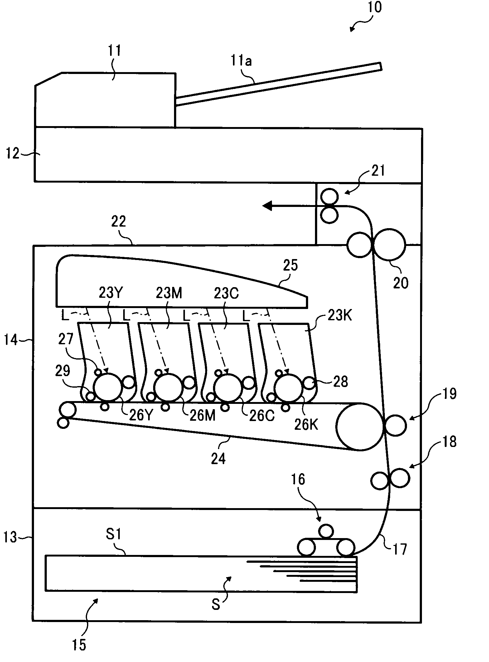
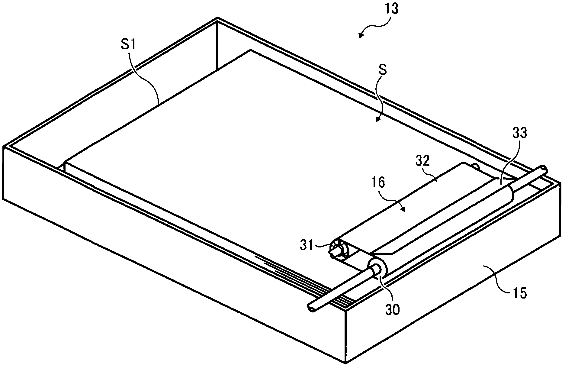
[0086] exist figure 1 Among them, the copying machine 10 as an image forming device includes an automatic document conveyance device that separates original documents one by one from the original document bundle placed in the original document tray 11a and automatically feeds them into the contact glass of the original document reading section 12. 11; the document reading part 12 that reads the document conveyed onto the contact glass by the automatic document conveying device 11; The image forming section (image forming apparatus) 14 of the captured image; has a sheet bundle S on which a plurality of sheets are placed, and feeds S1 located at the top of the sheet bundle ...

no. 2 Embodiment approach

[0151] Figure 14 , Figure 15 Shown is the second embodiment of the sheet feeding device and the image forming device according to the present invention. In this embodiment, a charging roller is used as a conductive member instead of the charging blade in the first embodiment. The same symbols are assigned to the same configurations in the embodiments, and description thereof will be omitted.

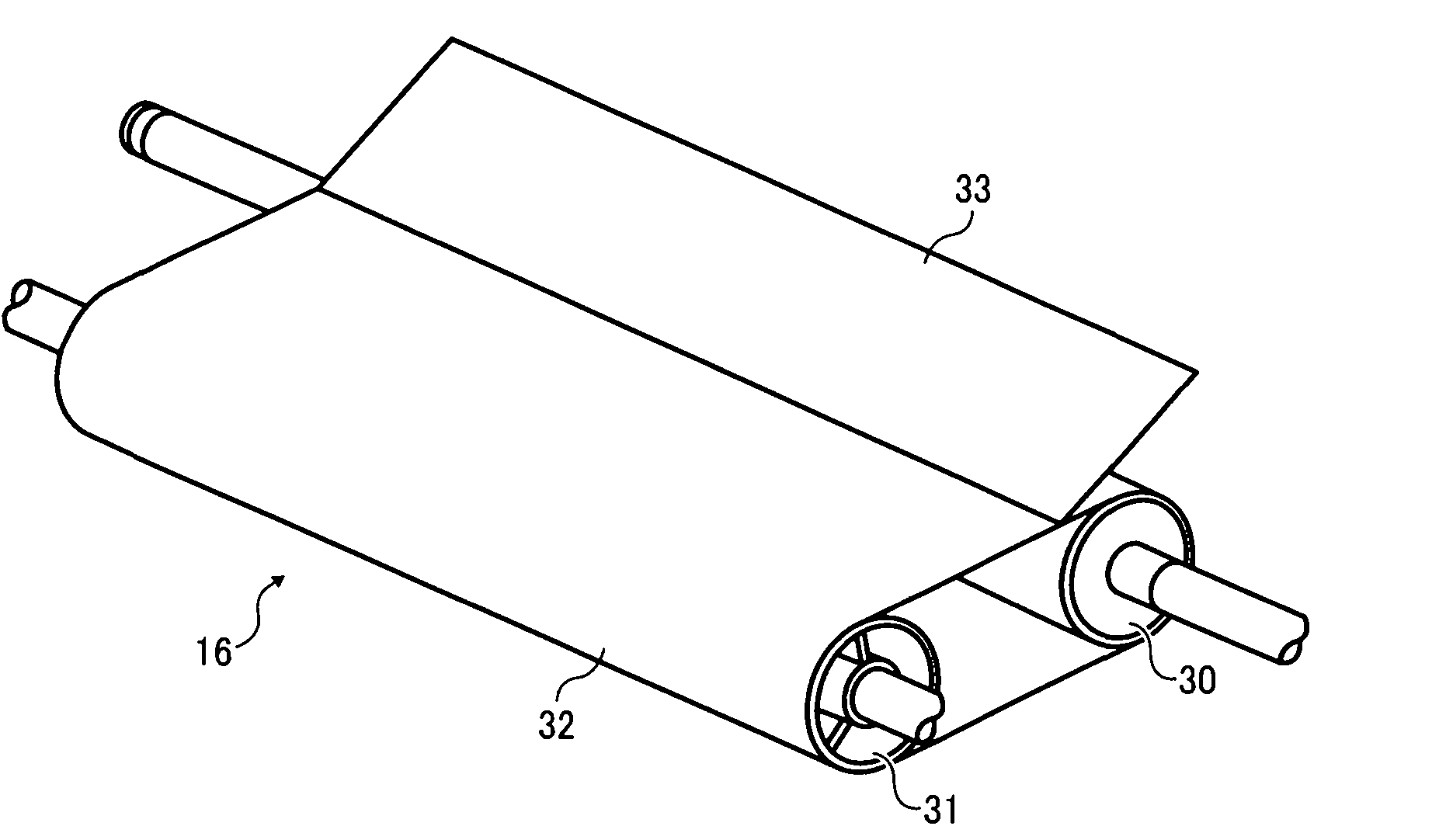
[0152] exist Figure 14 , Figure 15 Among them, the charging roller 71 as a charging member has an outer peripheral portion 71 a that forms a nip portion together with the endless belt 32 after being in contact with the endless belt 32 , and this outer peripheral portion 71 a constitutes a contact portion. In addition, the width|variety of a nipping part is called nipping width N hereafter.

[0153] Additionally, if Figure 15As shown, the charging roller 71 has the effect of forming a discharge that applies charges to the surface of the endless belt 32 by discharging between the...


PUM

PropertyMeasurementUnit
Thicknessaaaaaaaaaa

Abstract

The invention provides a sheet feeding unit and an image forming apparatus capable of reducing an electrical distance, even for a plurality of sheet kinds, capable of providing a sheet bundle carried in a sheet carrying component which is changed into stable relative to an environmental change or a period change, and capable of highly-speed and practically separating the sheet feeding unit in one piece with high reliability. An electrical scraper (33) is contacted with an endless belt (32); a small clearance G for applying a charge to a surface (32a) of the endless belt (32) is formed by discharging between the electrical scraper (33) and the endless belt (32), simultaneously forming a front end part (33a) of a clamping portion with the endless belt (32); and a basic electrical width H formed by a width N of the clamping part and the small clearance G is less than one half (1/2P) of a cycle length of an alternation charge applied to the endless belt (32) by the electrical scraper (33) so as to be less than the electrical width of the charge electrified with the same polarity in a surround moving direction of the endless belt (32).

Description

technical field [0001] The present invention relates to a sheet feeding device and an image forming device, such as a sheet feeding device that absorbs a sheet in an endless belt using static electricity and then feeds it, and an electrophotographic copying machine including the sheet feeding device , fax equipment, printing equipment, inkjet equipment and other image forming equipment. Background technique [0002] As sheet feeding equipment for image forming equipment such as electrophotographic copiers, facsimile equipment, printing equipment, inkjet equipment, etc., a pickup member formed of a roller or a belt made of a material with a high friction coefficient such as rubber is generally used. The friction feeding method. [0003] Although the friction feeding method has a simple structure, in order to obtain a large friction force, it is necessary to press the pick-up member into the surface of the sheet through a spring or the like. In addition, materials with a high...

Claims


Application Information

Patent Timeline
IPC IPC(8): B65H3/18B65H3/46
Inventor 桧垣秀人
Owner RICOH KK
Why Eureka
Try Eureka