Device for laying a unidirectional layer and a multi-axle knitting machine

A unidirectional and longitudinal technology, applied in warp knitting, flat warp knitting machine, knitting and other directions, can solve the problems of disturbing the quality of unidirectional yarn layers, falling, and being torn.

Active Publication Date: 2014-12-24
KARL MAYER TECH TEXTILIEN GMBH
View PDF3 Cites 0 Cited by
  • Summary
  • Abstract
  • Description
  • Claims
  • Application Information

AI Technical Summary

Problems solved by technology

In addition, there is a risk of being torn off on the fastening hooks of the conveyor chain
As a result, there is a greater risk of faults forming, which greatly disturb the knitting process and reduce the quality of the final unidirectional yarn layer produced.

Method used


Image

  • Device for laying a unidirectional layer and a multi-axle knitting machine
  • Device for laying a unidirectional layer and a multi-axle knitting machine
  • Device for laying a unidirectional layer and a multi-axle knitting machine

Examples


Embodiment Construction

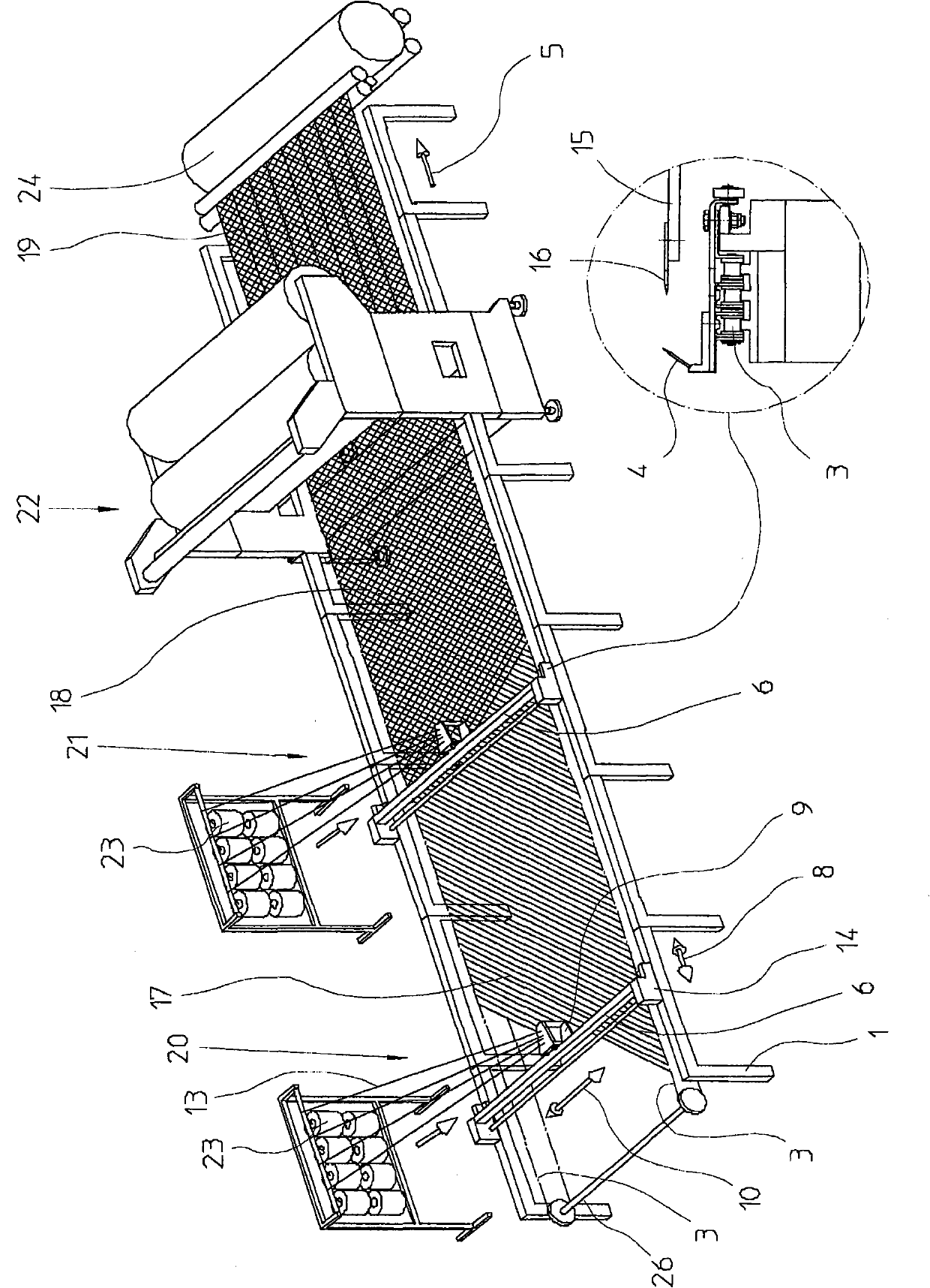
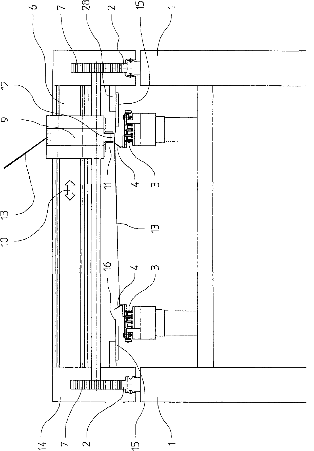
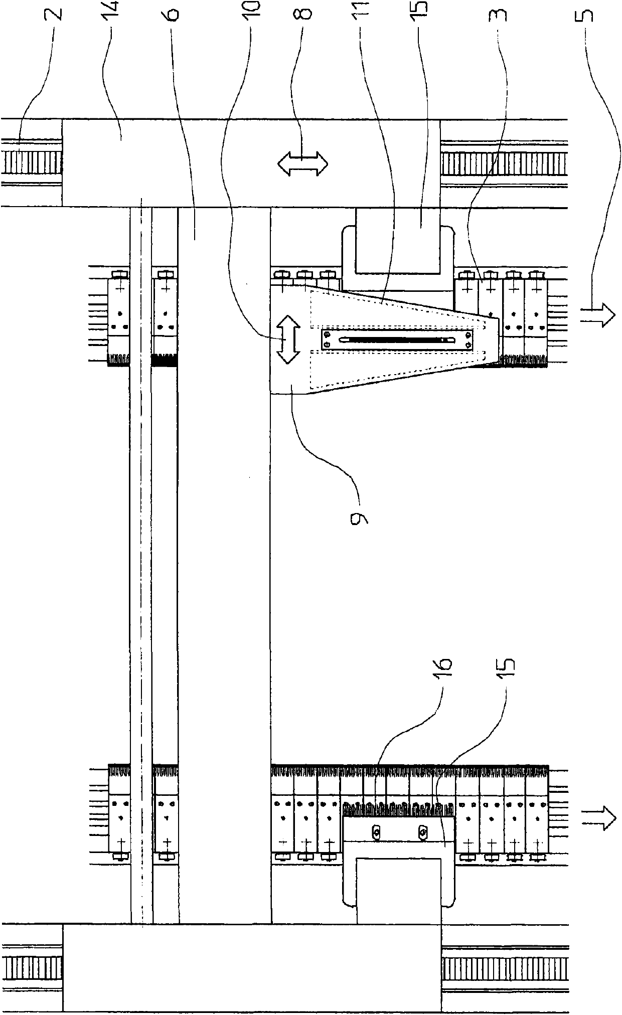
[0035] use figure 1 The multiaxial weaving machine schematically shown in produces a multiaxial yarn fabric in the form of a belt consisting of two unidirectional yarn layers. The multiaxial weaving machine has a frame consisting of two sides 1 spaced apart from one another and extends in the longitudinal direction of the tape yarn fabric to be produced. Two endless longitudinal conveyor belts 3 are arranged at a mutual transverse distance in the machine frame 1 , which are deflected on deflection axes 26 and are driven by invisible drives located in the connecting station 22 . The longitudinal conveyor belt 3 moves in the direction of travel 5 . In the example shown, the longitudinal conveyor belt 3 is designed in the form of a conveyor chain, on which there are conventional fastening hooks 4, see figure 1 Detail view shown enlarged at center lower right. In the example shown, only a single row of fastening hooks 4 is provided on each longitudinal conveyor belt 3 ; howev...


PUM


Abstract

#CMT# # / CMT# The device has a thread-guide whose motion trail is arranged at a motion plane parallel to a laying plane. A movable compressing comb bracket (15) is provided with a tooth part (16). The tooth part of the compressing comb bracket is engaged between yarns (31) of a yarn bunch extending next to a fixing hook row (4) at stage of traversing movement. The tooth part momently and synchronously moves with the thread-guide and compressed by the yarns until providing the tooth part to the fixing hook row. #CMT# : # / CMT# An independent claim is also included for a multi-axial knitting machine. #CMT#USE : # / CMT# Device for transmitting one-way layers at two longitudinal transmission belts of a multi-axial knitting machine (claimed). #CMT#DESCRIPTION OF DRAWINGS : # / CMT# The drawing shows a side view of a device for transmitting one-way layers at two longitudinal transmission belts of a multi-axial knitting machine. 4 : Fixing hook row 12 : Reed 15 : Movable compressing comb bracket 16 : Tooth part 31 : Yarns.

Description

technical field [0001] The invention relates to a device for laying layers of unidirectional yarns on two longitudinal conveyor belts and a multiaxial weaving machine. Background technique [0002] According to the device described in the preamble of claim 1, such as known from DE10049280A1 and in the literature by means of Figure 4 and 4 aDetailed description. Furthermore, the yarns are moved transversely back and forth between the two longitudinal conveyor belts in groups (gruppenweise) in the form of yarn bundles, and also in the turning area when reaching the respective longitudinal conveyor belts. Definitions "Transverse" here means a direction perpendicular or oblique to the direction of the longitudinal conveyor belt. Thus, the yarn bundles are laid in groups parallel to each other lying on top of each other, and a traverse movement is carried out in the turning area. [0003] In accordance with DE10049280A1 the Figure 4 and 4 In the embodiment of a, the thread ...

Claims


Application Information

Patent Timeline
Patent Type & Authority Patents(China)
IPC IPC(8): D04B23/12D04B23/10D04B23/22
CPCD04B23/12
Inventor 莱纳·索依斯
Owner KARL MAYER TECH TEXTILIEN GMBH
Why Eureka
Try Eureka