Formation factor determining method and oil saturation determining method

A technology of formation factor and porosity, which is applied in the field of determination of oil saturation and low permeability reservoir formation factor, can solve the problems of large error in calculating oil saturation and inaccurate determination of formation factor, etc., and achieve accurate results

Active Publication Date: 2010-11-24
PETROCHINA CO LTD
View PDF9 Cites 39 Cited by
  • Summary
  • Abstract
  • Description
  • Claims
  • Application Information

AI Technical Summary

Problems solved by technology

[0006] In view of the problems existing in the prior art, the purpose of the present invention is to provide a formation factor measurement and determination method and an oil saturation determination method to solve the problem of inaccurate determination of formation factors and large errors in calculating oil saturation in the prior art. defect

Method used


Image

  • Formation factor determining method and oil saturation determining method
  • Formation factor determining method and oil saturation determining method
  • Formation factor determining method and oil saturation determining method

Examples


Embodiment 1

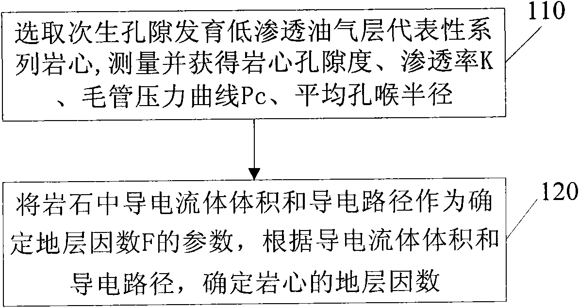
[0017] Please refer to figure 1 , figure 1 is a flow chart of the formation factor determination method of the present invention, such as figure 1 Shown, formation factor determining method of the present invention comprises steps:

[0018] Step 110: Select a representative series of cores from low-permeability oil and gas layers with secondary pores, and obtain core porosity φ, permeability K, capillary pressure curve Pc, and average pore throat radius through measurement where the porosity φ reflects the volume of the conductive fluid in the rock, reflect the conductive path;

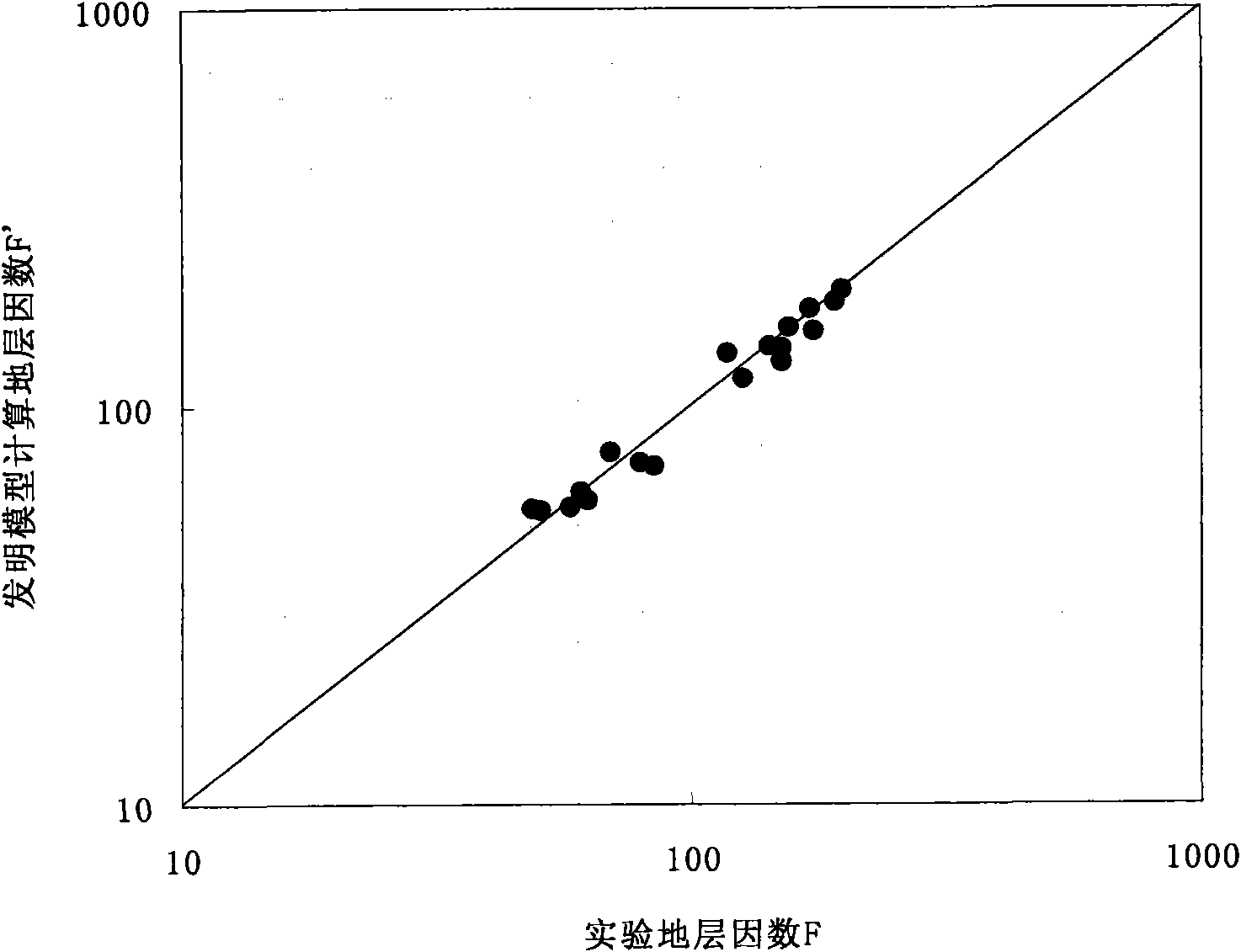
[0019] Select 18 core samples from two layers in two blocks (porosity between 5.3% and 14.4%, permeability between 0.1×10 -3 μm 2 ~26.0×10 -3 μm 2 Between), according to the "core analysis method (SY / T5336-2006)" and "rock capillary pressure curve determination (SY / T5346-2005)" standard procedures to conduct experiments, measure and calculate the porosity φ, Permeability K, capillary pressur...

Embodiment 2

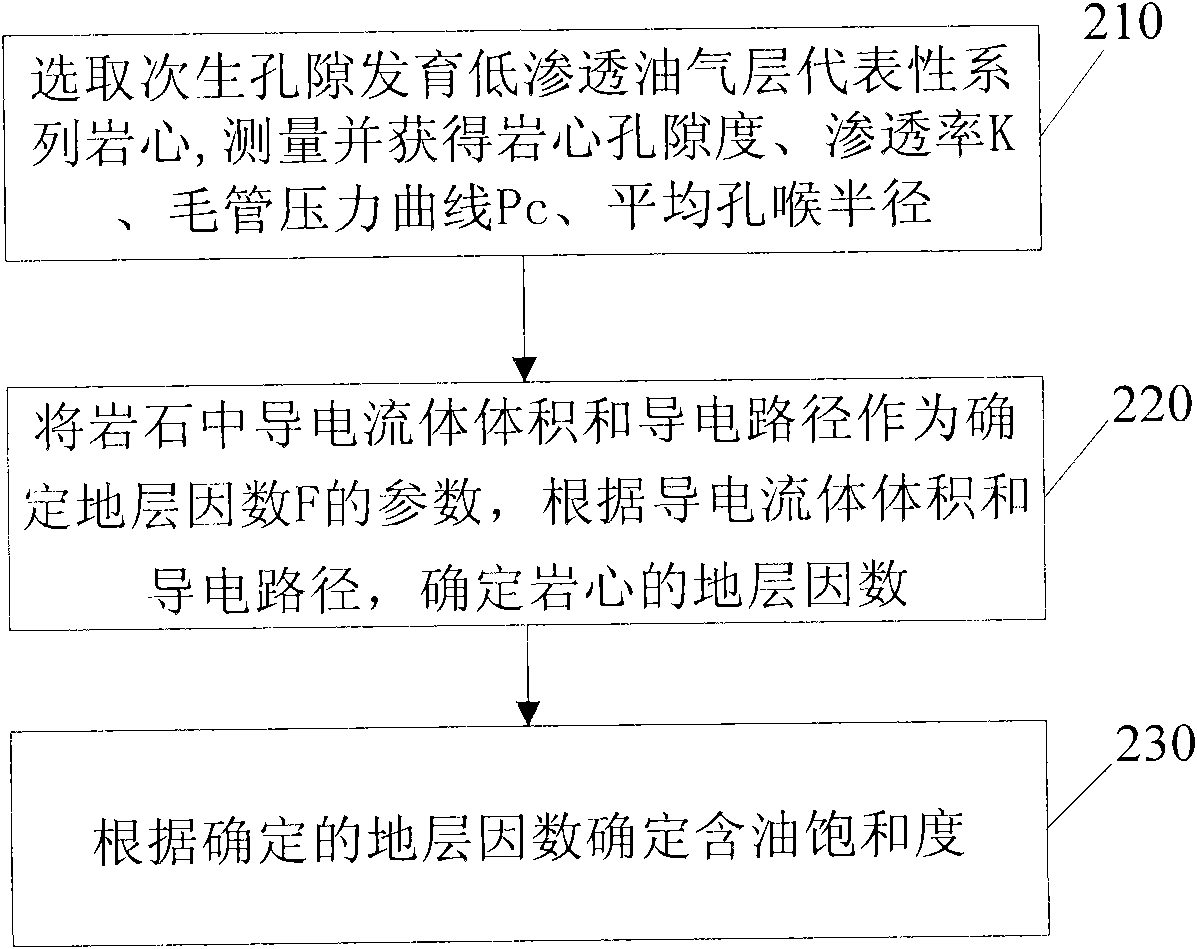
[0035] Please refer again figure 2 , figure 2 It is a flowchart of the method for determining oil saturation of the present invention, such as figure 2 Shown, the method for determining oil saturation of the present invention comprises steps:

[0036] Step 210: Select a representative series of cores from low-permeability oil and gas layers with secondary pores, and obtain core porosity φ, permeability K, capillary pressure curve Pc, and average pore throat radius through measurement where the porosity φ reflects the volume of the conductive fluid in the rock, reflect the conductive path;

[0037] Step 220: The volume of the conductive fluid in the rock and the conductive path are used as parameters for determining the formation factor F, and the specific relationship is: According to the conductive fluid volume and conductive path, the formation factor is determined; the coefficients a, b, and c are obtained through calibration of core data.

[0038] The specific s...


PUM


Abstract

The invention provides a formation factor determining method and an oil saturation determining method, wherein the formation factor determining method comprises the following steps of: selecting a representative series core of a secondary pore development low-percolation oil-gas layer; measuring and obtaining a core porosity degree phi, a percolation rate K, a capillary pressure curve Pc and an average pore-throat semidiameter, wherein the core porosity degree phi is used for reflecting conductive fluid volume and a conductive path in rock, and the conductive fluid volume and the conductive path in the rock are used as parameters for determining a formation factor F. The invention has the specific relational expression: determining the formation factor according to the conductive fluid volume and the conductive path, and factors a, b and c are obtained by calibrating core data. The invention introduces the conductive fluid volume and the conductive path as the parameters to determine the formation factor, and a formation factor calculation result more conforms to an actual formation condition for determining a more accurate oil saturation result.

Description

technical field [0001] The invention relates to a well logging evaluation technology in petroleum exploration, in particular to a method for determining formation factors of low-permeability reservoirs and a method for determining oil saturation based on conductive fluid volume and conductive path, which are applied in well logging interpretation. Background technique [0002] The main task of well logging interpretation is to identify and quantitatively evaluate oil and gas layers. The electrical properties of water-saturated rocks represented by Archie’s formula and its extended forms are the basis for quantitatively evaluating oil saturation using well logging data. In the development of quantitative interpretation of well logging played an important role in. The classic Archie's formula is suitable for pure sandstone with intergranular pores and good porosity and permeability. It has a relatively simple pore size distribution, good pore-throat matching relationship, and ...

Claims


Application Information

Patent Timeline
Patent Type & Authority Applications(China)
IPC IPC(8): E21B49/00E21B47/00G01V3/18
Inventor 李长喜张龙海王昌学李潮流李霞
Owner PETROCHINA CO LTD
Why Eureka
Try Eureka