Method for improving imaging precision of deep reflection seismic data

A technology of seismic data and deep reflection, applied in seismic signal processing and other directions, can solve the problems of ignoring the lateral change of velocity and the accuracy error of rock structure imaging, and achieve the effect of improving the accuracy and eliminating the error.

Pending Publication Date: 2022-07-26
GUANGZHOU MARINE GEOLOGICAL SURVEY +1
View PDF0 Cites 0 Cited by
  • Summary
  • Abstract
  • Description
  • Claims
  • Application Information

AI Technical Summary

Problems solved by technology

[0003] However, the current technical methods for data processing of deep reflection seismic sections are all based on pre-stack time migration, but time migration ignores the lateral change of velocity, which will cause large errors in the accuracy of rock structure imaging

Method used


Image

  • Method for improving imaging precision of deep reflection seismic data
  • Method for improving imaging precision of deep reflection seismic data
  • Method for improving imaging precision of deep reflection seismic data

Examples


Embodiment 1

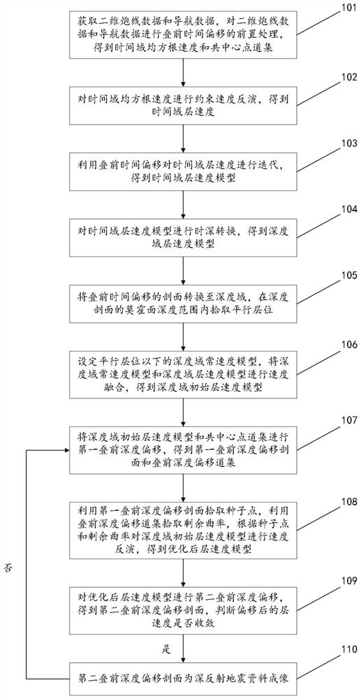
[0066] figure 1 It is a schematic flowchart of Embodiment 1 of the method for improving the imaging accuracy of deep reflection seismic data shown in the embodiment of the present application;

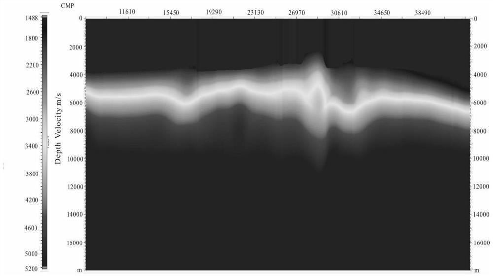
[0067] figure 2 is a schematic diagram of the velocity model of the depth domain layer after time-to-depth conversion shown in the embodiment of the present application;

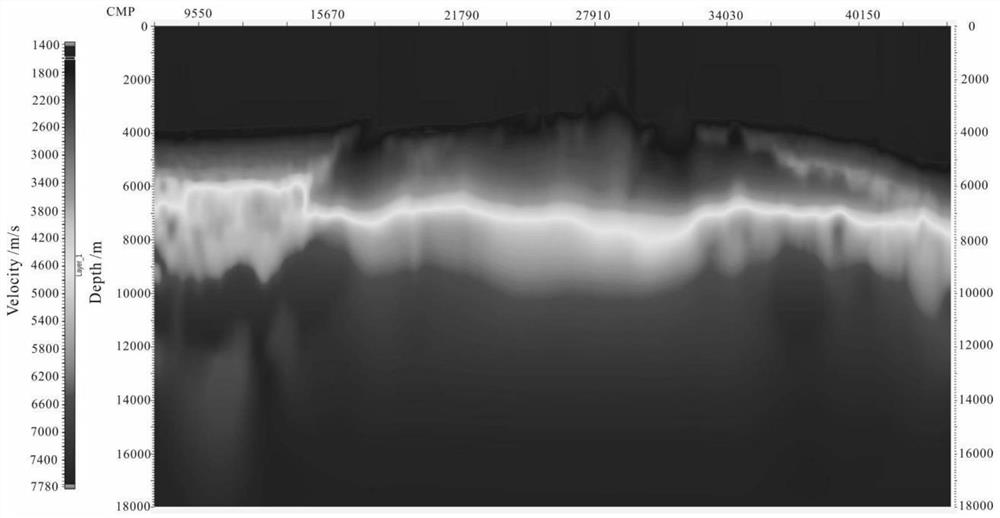
[0068] image 3 is the schematic diagram of the optimized layer velocity model shown in the embodiment of the present application;

[0069] Figure 4 It is a schematic diagram of deep reflection seismic data imaging shown in the embodiment of the present application.

[0070] see Figure 1-4 , the first embodiment of the method for improving the imaging accuracy of deep reflection seismic data in the embodiment of the present application includes:

[0071] 101. Acquire two-dimensional shot line data and navigation data, perform pre-stack time migration preprocessing on the two-dimensional shot line data and na...

Embodiment 2

[0096] In practical applications, on the basis of Embodiment 1, this embodiment details how to fuse the velocity of the depth domain constant velocity model and the depth domain layer velocity model to obtain the depth domain initial layer velocity model.

[0097] Figure 5 This is a schematic flowchart of Embodiment 2 of the method for improving the imaging accuracy of deep reflection seismic data shown in the embodiment of the present application;

[0098] Image 6 is a schematic diagram of the velocity model of the first depth domain layer shown in the embodiment of the present application;

[0099] Figure 7 is a schematic diagram of the first depth domain constant velocity model shown in the embodiment of the present application;

[0100] Figure 8 is a schematic diagram of the velocity model of the first fusion layer shown in the embodiment of the present application;

[0101] Figure 9 is a schematic diagram of the velocity model of the second depth domain layer s...

Embodiment 3

[0123] In practical applications, on the basis of the above embodiments, this embodiment introduces in detail how to obtain the optimized layer velocity model.

[0124] Figure 12 This is a schematic flowchart of Embodiment 3 of the method for improving the imaging accuracy of deep reflection seismic data shown in the embodiment of the present application;

[0125] Figure 13 are schematic diagrams of residual curvature profiles of different resolutions shown in the embodiments of the present application;

[0126] Figure 14 It is a schematic diagram of picking seed points on the first pre-stack depth migration profile shown in the embodiment of the present application.

[0127] see Figure 3-4 Immediately Figure 12-14 (in, Figure 12 The resolution and the residual curvature in the middle are increased in sequence from top to bottom), the third embodiment of the method for improving the imaging accuracy of deep reflection seismic data in the embodiment of the present a...


PUM


Abstract

The invention relates to a method for improving imaging precision of deep reflection seismic data. The method comprises the following steps: performing first pre-stack depth migration on a depth domain initial interval velocity model and a common midpoint gather to obtain a first pre-stack depth migration profile and a pre-stack depth migration gather; picking up a seed point by using the first pre-stack depth migration profile, picking up a residual curvature by using the pre-stack depth migration gather, and performing velocity inversion on the depth domain initial interval velocity model according to the seed point and the residual curvature to obtain an optimized interval velocity model; and performing second pre-stack depth migration on the optimized interval velocity model to obtain a second pre-stack depth migration profile, and if the interval velocity after migration converges, determining that the second pre-stack depth migration profile is a deep reflection seismic data image. According to the scheme provided by the invention, the imaging precision of the rock deep structure can be better improved, and the rock circle deep structure characteristics are revealed.

Description

technical field [0001] The present application relates to the technical field of seismic data imaging, and in particular, to a method for improving the imaging accuracy of deep reflection seismic data. Background technique [0002] The deep seismic reflection profile detection technology is one of the most effective technologies for detecting the fine structure of the lithosphere recognized by the international geoscience community, and it has played an important role in revealing crustal rock deformation and tectonic traces, regional tectonic events, and even important connections between the lithosphere and the upper mantle. . For deep reflection seismic data, due to the long recording time, the seismic signal weakens with the increase of the detection depth, and the external background noise energy has nothing to do with the recorded depth, so the deep seismic reflections are actually weak reflections, and the signal-to-noise ratio of the data very low. In order to bett...

Claims


Application Information

Patent Timeline
Patent Type & Authority Applications(China)
IPC IPC(8): G01V1/28G01V1/30
CPCG01V1/282G01V1/303
Inventor 薛花杜民张宝金顾元刘斌徐云霞
Owner GUANGZHOU MARINE GEOLOGICAL SURVEY
Why Eureka
Try Eureka