Engine transient air inflow estimation method based on model

An engine and air intake technology, applied in engine control, machine/engine, electrical control, etc., can solve problems such as poor engine charging efficiency change trend accuracy, poor air volume estimation accuracy, etc.

Active Publication Date: 2010-11-24
FAW GROUP
View PDF4 Cites 29 Cited by
  • Summary
  • Abstract
  • Description
  • Claims
  • Application Information

AI Technical Summary

Problems solved by technology

[0004] Since the known gradient is used to directly represent the change trend of the engine charging efficiency, the accuracy is very poor, an

Method used


Image

  • Engine transient air inflow estimation method based on model
  • Engine transient air inflow estimation method based on model
  • Engine transient air inflow estimation method based on model

Examples


Embodiment Construction

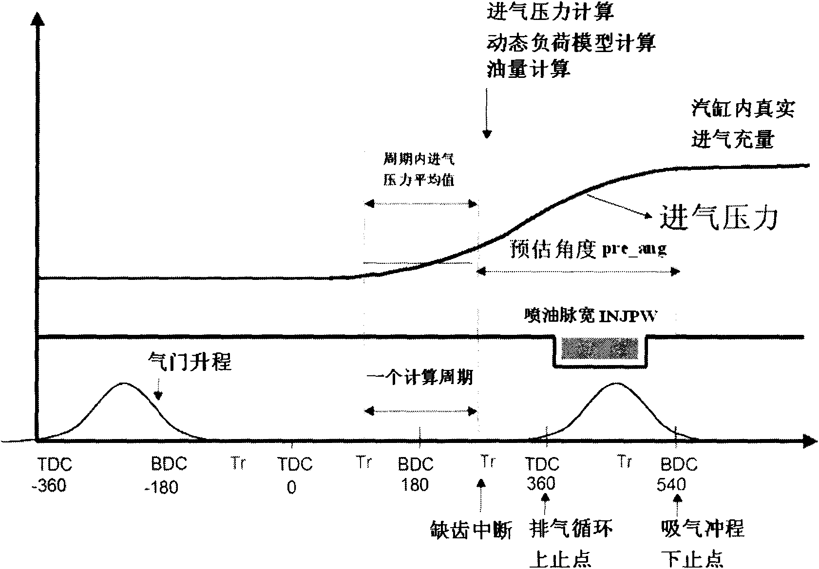
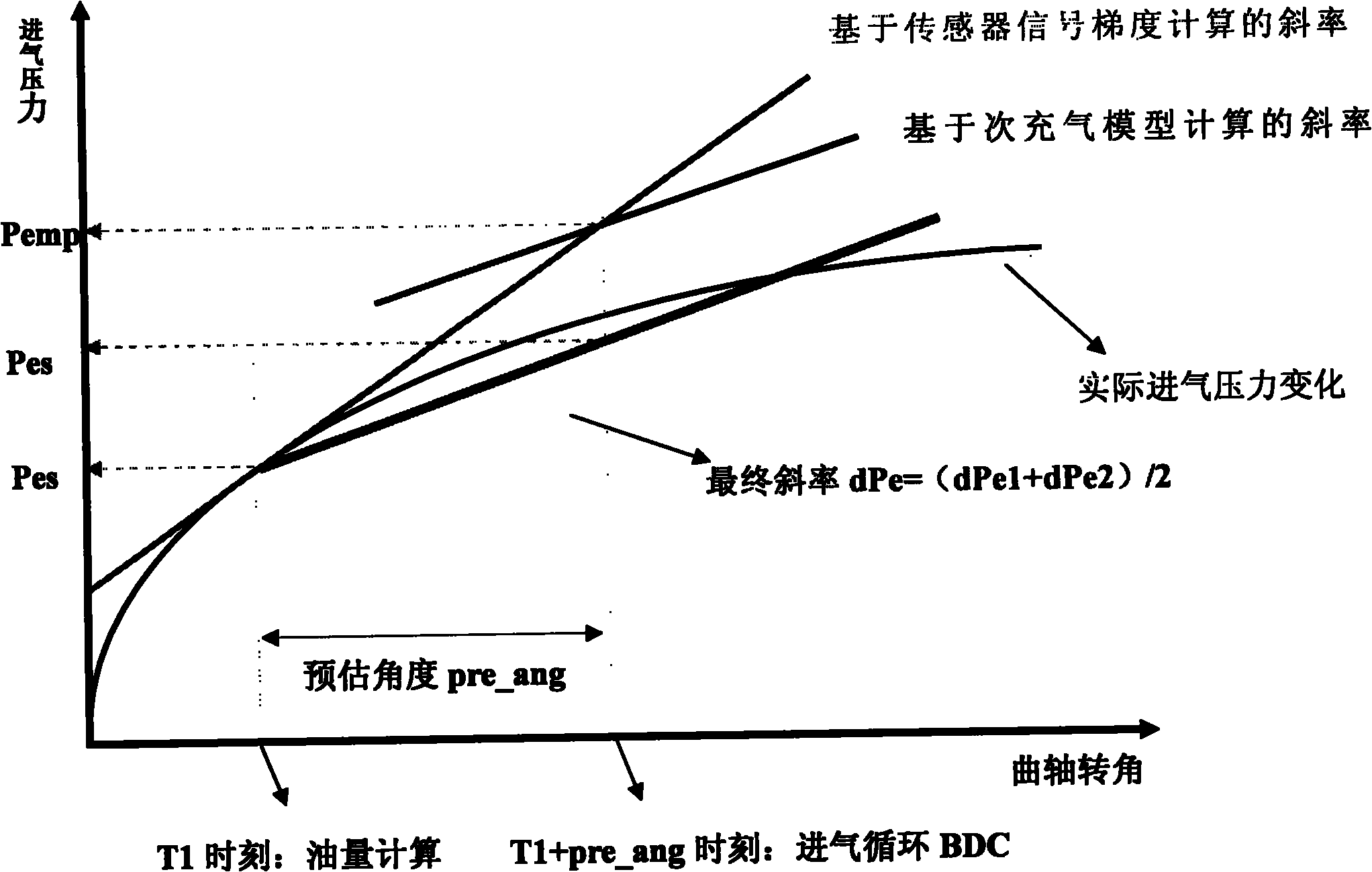
[0049] Below in conjunction with accompanying drawing, the present invention is further described: a kind of model-based engine transient air intake quantity estimation method, it is characterized in that: be made up of following several physical models and computing method; Processing, main charging model based on velocity density method, secondary charging model based on throttle flow characteristics, throttle angle estimation model, intake pipe dynamic load model, and pre-estimation calculation of charge coefficient; the calculation process is sequentially performed in a 10ms task Calculate the secondary charging model, throttle angle prediction model, calculate the current intake pressure, main charging model, intake pipe dynamic load model and charge coefficient prediction model when the missing tooth is interrupted.

[0050] Specifically include the following:

[0051] 1. Define the charge coefficient

[0052] Single-cylinder air intake quality and under standard conditio...


PUM


Abstract

The invention relates to an engine transient air inflow estimation method based on model. The invention is characterized in that the method includes the following physical models and computing methods: acquisition and processing of inlet pressure sensor signal, a main aeration model based on speed-density method, a secondary aeration model based on throttle valve flow characteristic, a throttle valve angle estimation model, an inlet air pipe dynamic load model and estimation of volumetric efficiency; calculation process is that the secondary aeration model and the throttle valve angle estimation model are sequentially calculated in 10ms task and the current inlet pressure, the main aeration model, the inlet air pipe dynamic load model and the volumetric efficiency estimation model are calculated in tooth-missing interruption. Control accuracy is improved, thus avoiding the phenomena that torque responsiveness is poor under transient working condition and emission is worsen.

Description

technical field [0001] The invention relates to a method for estimating the transient intake air quantity of an engine based on a model, and belongs to the field of automotive electronic software development. Background technique [0002] For volume regulation engine control, the fuel quantity is generally calculated according to the amount of intake air and the target air-fuel ratio. But for general port injection engines, the fuel injection time of the current cycle should be earlier than the completion time of the intake air quantity (it is generally considered that the intake air is completed at the bottom dead center of the intake cycle, but for pre-mixing, the fuel injection is generally injected into the intake manifold in advance Tube). Such as figure 1 As shown, the intake is completed at the bottom dead center of the intake stroke, and the fuel injection will be completed before that. Fuel concentration can be accurately guaranteed if the engine is operated unde...

Claims


Application Information

Patent Timeline
IPC IPC(8): F02D41/18G06F19/00
Inventor 王超华东旭
Owner FAW GROUP
Why Eureka
Try Eureka