Control method of dynamic aperture based on ultrasonic imaging system

An ultrasonic imaging system and dynamic aperture technology, applied in the direction of sound wave re-radiation, radio wave measurement system, instrument, etc., can solve the problems of mechanical and cumbersome, weak imaging ability, and impact on imaging quality, so as to improve imaging ability and eliminate dead area, improve the effect of overall imaging quality

Inactive Publication Date: 2010-11-24
CHONGQING UNIV
View PDF4 Cites 9 Cited by
  • Summary
  • Abstract
  • Description
  • Claims
  • Application Information

AI Technical Summary

Problems solved by technology

However, there are few reports on this aspect of research. Usually, in engineering implementation, it is mainly through manual methods to carry out repeated experiments to correct and adjust the control parameters of dynamic aperture, so as to obtain a set of better dynamic aperture control parameters. The entire implementation process is very mechanical and cumbersome. If the probe parameters and detection objects change, it is necessary to repeat the mechanical and tedious experimental work to obtain a set of dynamic aperture control parameters again; and in the existing dynamic aperture control technology, ultrasonic imaging The imaging ability of the system for the area between the scan lines is weak, which has a certain impact on the overall imaging quality

Method used


Image

  • Control method of dynamic aperture based on ultrasonic imaging system
  • Control method of dynamic aperture based on ultrasonic imaging system
  • Control method of dynamic aperture based on ultrasonic imaging system

Examples


Embodiment Construction

[0027] Preferred embodiments of the present invention will be described in detail below.

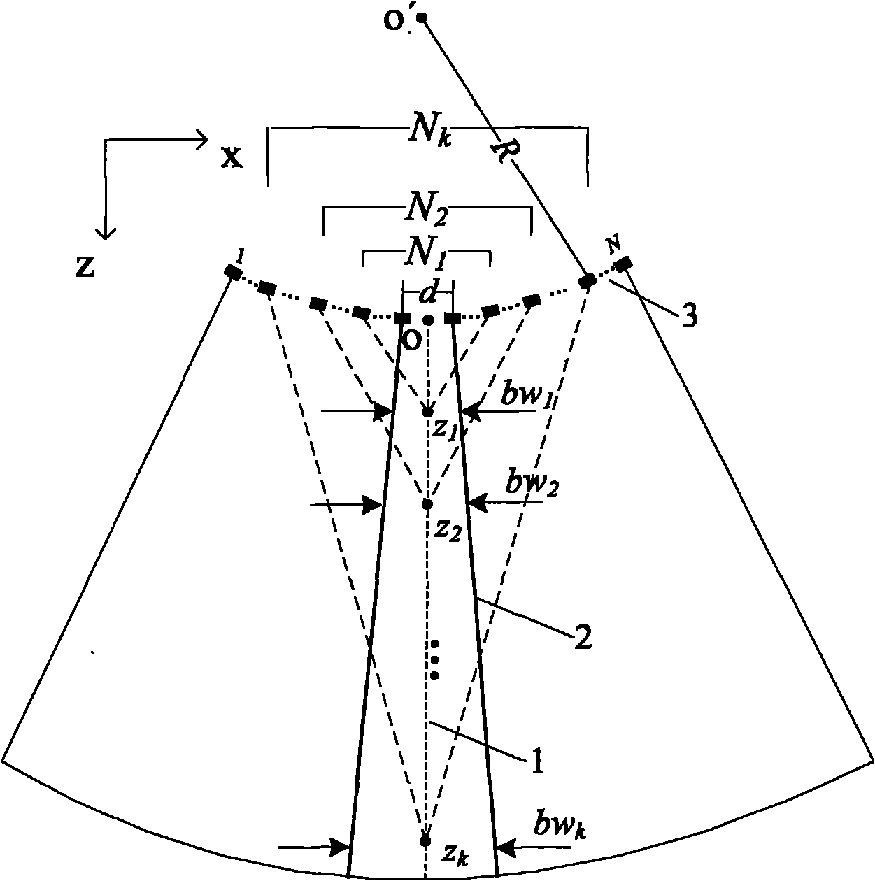
[0028] see figure 1 , where o is the coordinate origin, d is the array element spacing, R is the curvature radius of the probe, 3 is the probe array element, and the number of array elements is N. figure 1 The beam 2 shown in is the desired effect after dynamic control. The beam width is the corresponding width when the beam drops 3dB to both sides relative to the center scan line 1.

[0029] This embodiment is based on the dynamic aperture control method of the ultrasonic imaging system, and for the ultrasonic imaging of the convex array probe, the sequential scanning method includes the following steps:

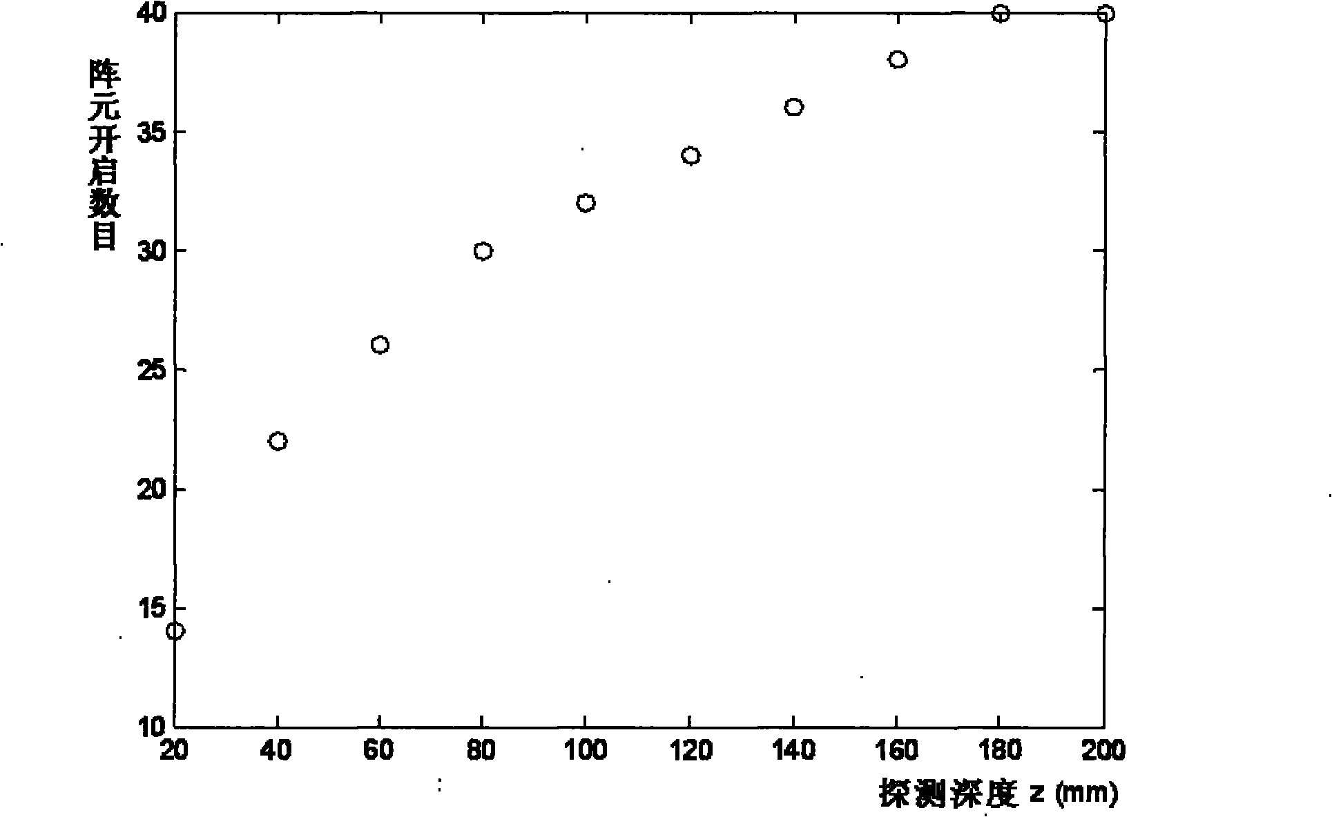
[0030] 1) Obtain the ultrasonic echo signal, analyze the detection depth of the ultrasonic echo signal, and evenly segment the detection depth by the following formula to obtain a plurality of uniformly distributed depths:

[0031] z k =depth*k / K, k=1, 2, 3,..., K;

[0032] In the...


PUM


Abstract

The invention belongs to the ultrasonic imaging technical field, and in particular relates to a control method of a dynamic aperture based on an ultrasonic imaging system, which aims at ultrasonic imaging in a sequential scanning mode by virtue of a convex lens probe. The method comprises the following steps: uniformly segmenting depths of investigation and then calculating beam width which can fully cover the area between two adjacent scanning lines under different depths according to known probe parameters such as curvature radius and array element spacing of the probe; and reversely calculating the number of array elements which need to be started by the probe under the corresponding depths according to the beam width value with different depths of investigation and a probe normalized directivity function with a discrete array. In the control method of the dynamic aperture, the beam width which can fully cover the area between the two adjacent scanning lines can be obtained throughcalculation to eliminate parts of dead zones which can not be imaged and improve imaging capability of the system on the area among the scanning lines, thus effectively enhancing the overall imaging quality of the ultrasonic system.

Description

technical field [0001] The invention belongs to the technical field of ultrasonic imaging, and in particular relates to a dynamic aperture control method based on an ultrasonic imaging system. Background technique [0002] In the ultrasonic imaging system, as the depth of the received ultrasonic echo signal increases, the process of dynamically controlling the opening of the receiving element of the probe is called dynamic aperture control technology. [0003] Dynamic aperture control technology is an important link in the ultrasound imaging system and has many advantages. However, there are few reports on this aspect of research. Usually, in engineering implementation, it is mainly through manual methods to carry out repeated experiments to correct and adjust the control parameters of dynamic aperture, so as to obtain a set of better dynamic aperture control parameters. The entire implementation process is very mechanical and cumbersome. If the probe parameters and detecti...

Claims


Application Information

Patent Timeline
Patent Type & Authority Applications(China)
IPC IPC(8): G01S7/52G01S15/89
Inventor 王平许琴王伟明陈民铀何为
Owner CHONGQING UNIV
Why Eureka
Try Eureka