Dielectric resonator, flexible conductive shielding part and dielectric filter

A dielectric resonator and dielectric filter technology, which is applied in the direction of resonators, electrical components, waveguide devices, etc., can solve the problems of uneven force, temperature change, assembly error, etc., achieve reliable grounding, improve performance indicators, reduce cost effect

Inactive Publication Date: 2010-11-24
ANHUI TATFOOK TECH CO LTD
View PDF9 Cites 13 Cited by
  • Summary
  • Abstract
  • Description
  • Claims
  • Application Information

AI Technical Summary

Problems solved by technology

[0005] In the process of researching the prior art, the inventors of the present invention found that in the prior art, in order to solve the grounding problem on the upper surface of the dielectric resonant column, a conductive elastic body was used to contact the cover plate through the conductive elastic body, and then pass The cavity is grounded, but du

Method used


Image

  • Dielectric resonator, flexible conductive shielding part and dielectric filter
  • Dielectric resonator, flexible conductive shielding part and dielectric filter
  • Dielectric resonator, flexible conductive shielding part and dielectric filter

Examples


Embodiment 1

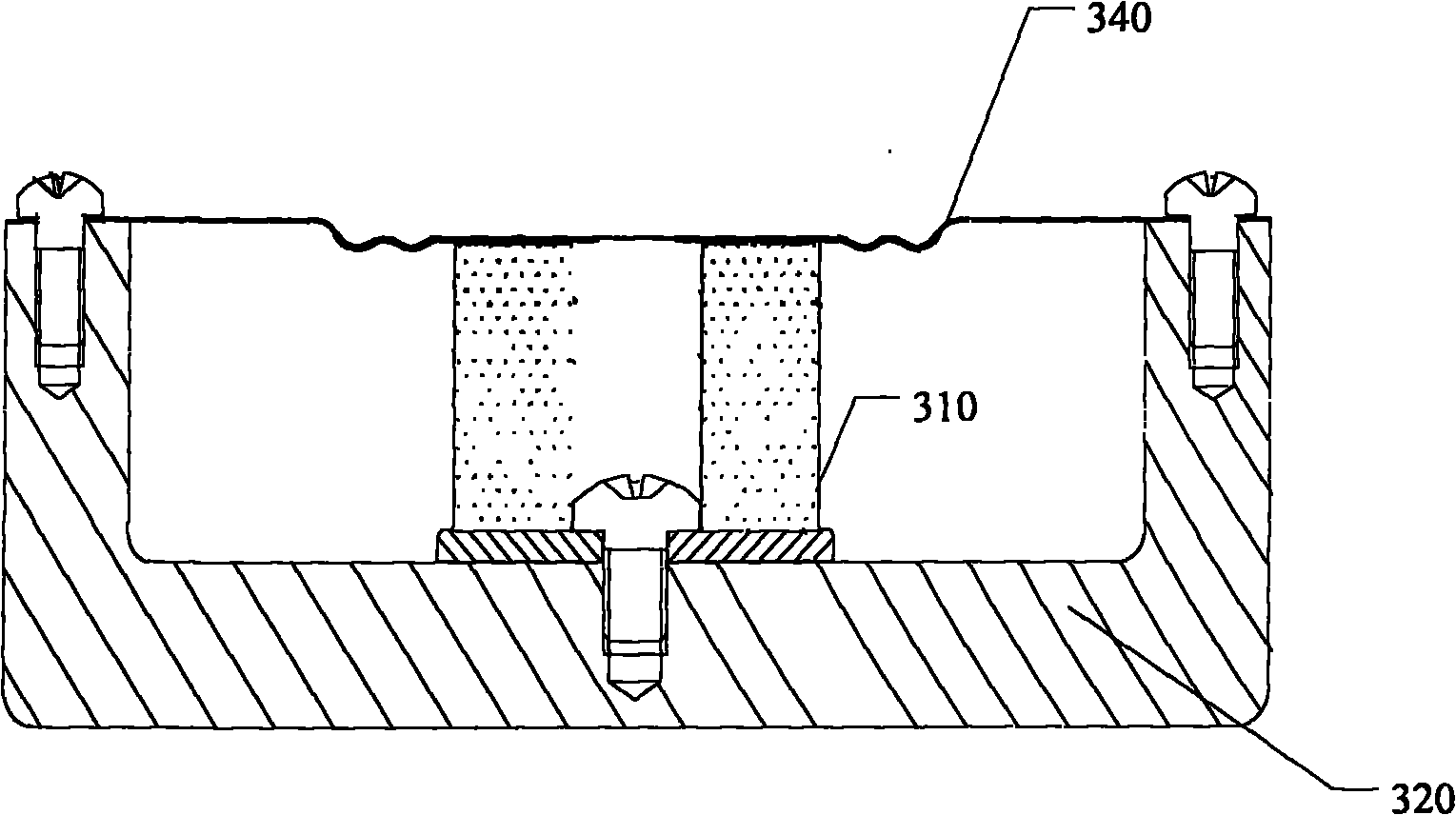
[0023] Embodiment 1. A dielectric resonator, as shown in FIG. 3(a), includes:

[0024] A dielectric resonance column 310 and a cavity 320, the dielectric resonance column 310 is disposed in the cavity 320, and further includes: an elastic conductive shield 340, the elastic conductive shield 340 seals the cavity 320 to form a resonance cavity, The elastic conductive shield 340 is in elastic contact with the dielectric resonance column 310 , so that the upper surface of the dielectric resonance column 310 is directly connected to the ground through the elastic conductive shield 340 .

[0025] As shown in Figure 3(b), the dielectric resonance column 310 provided in this embodiment may also include: a reinforcement 330, and the specific elastic conductive shield 340 may include an elastic shielding area 341 and a common shielding area 342, and the elastic conductive shielding A through hole is provided on the common shielding area of ​​the elastic conductive shielding part 340, an...

Embodiment 2

[0034] Embodiment 2. An elastic conductive shield is applied to a dielectric filter. The elastic conductive shield seals the cavity to form a resonant cavity. The schematic diagram of the structure is as follows Figure 4 As shown, it includes: an elastic shielding area 341 and a common shielding area 342, the elastic shielding area 341 is provided with a through hole 343, which is used for a screw to pass through the through hole, and the common shielding area of ​​the elastic conductive shield It is locked between the reinforcing piece and the cavity to realize the sealing of the cavity by the elastic conductive shielding component.

[0035] It can be understood that a through hole 344 is provided in the middle of the existing elastic shielding area, through which the tuning screw for the dielectric filter passes. The elastic shielding area and the common shielding area can be integrally formed. Specifically, stamping can be used to realize the elastic shielding area and thr...

Embodiment 3

[0037] Embodiment 3, an elastic conductive shielding member, the structure schematic diagram is as follows Figure 5 As shown (only part of the structure is shown in the figure), the elastic conductive shield includes a plurality of elastic shielding regions 510, and the plurality of elastic shielding regions are connected by the common shielding region 520, and each elastic shielding region 510 is connected to the dielectric filter Corresponds to the position of the inner dielectric resonant column.

[0038] Specifically, the elastic conductive shielding member can be integrally formed by stamping or other processes. For example, the plurality of elastic shielding regions and the through holes for the screws to pass through can be punched out by one or more times of punching. Specifically, in the design, the size of the elastic conductive shield is generally set to be equivalent to the size of the reinforcement, directly replacing the function of the original cover plate, fo...


PUM


Abstract

The invention discloses a dielectric resonator, a flexible conductive shielding part and a dielectric filter. The dielectric resonator provided by the embodiment of the invention comprises a dielectric resonance column, a cavity which is provided with the dielectric resonance column and the flexible conductive shielding part, wherein the flexible conductive shielding part seals the cavity to form a resonance cavity, and is flexibly contacted with the dielectric resonance column, so that the upper surface of the dielectric resonance column is directly earthed and conducted through the flexible conductive shielding part. Because the flexible conductive shielding part is adopted to directly seal the cavity to form the resonance cavity, the flexible conductive shielding part replaces the function of an original cover plate so as to reduce product cost; and meanwhile, the upper surface of the dielectric resonance column is directly earthed through the flexible conductive shielding part, so the earthing is more reliable, and the performance index of the dielectric resonator is improved.

Description

technical field [0001] The invention relates to the technical field of dielectric filters, in particular to a dielectric resonator, an elastic conductive shield and a dielectric filter. Background technique [0002] Dielectric filters are designed and manufactured using the characteristics of low loss, high dielectric constant, frequency temperature coefficient and thermal expansion coefficient of dielectric ceramic materials, and can withstand high power. It is characterized by low insertion loss and good power resistance. [0003] see figure 1 , which is a schematic diagram of a TM (transverse magnetic, transverse magnetic) mode dielectric filter, which is mainly composed of a dielectric resonance column 101 and a metal cavity 102 . It is very important that the upper and lower ends of the dielectric resonant column of the resonator in the TM mode dielectric filter are well grounded, otherwise the performance of the filter will be affected. [0004] Another existing diel...

Claims


Application Information

Patent Timeline
IPC IPC(8): H01P7/10H01P1/207
CPCH01P1/2084H01P7/10
Inventor 孙尚传童恩东
Owner ANHUI TATFOOK TECH CO LTD
Why Eureka
Try Eureka