Optical fiber connection relation checking method and device

A technology of optical fiber connection and inspection method, which is applied in the field of communication, and can solve the problems of failure to find the connection relationship between U1 and U2 upstream and downstream, incorrect detection results, high cost of external or built-in OSA units, etc.

Inactive Publication Date: 2010-11-24
江苏联智科技服务有限公司
View PDF2 Cites 4 Cited by
  • Summary
  • Abstract
  • Description
  • Claims
  • Application Information

AI Technical Summary

Problems solved by technology

[0004] In the existing technology, each network element or single board needs to be externally connected or built-in OSA instrument, and the OSA function is used to determine whether the optical fiber connection is correct. When a new optical fiber connection is introduced, the detection result may be incorrect due to the wrong optical fiber connection, and the external or The cost of the built-in OSA unit is relatively high, and the optical signal needs to be sent from the upstream NE to the local NE for detection. Please refer to figure 1 , if the upstream and downstream connections of U1 and U2 in the figure are wrong, the actual optical signal transmission will become: the optical signal sent by the light source is sent to U2 first, and then sent from U2 to U1, and the optical fiber connection relationship is checked by the above-mentioned prior art method , it can still be detected that both U1 and U2 receive optical signals with wavelengths of λ1 ~ λ4, so that the connection relationship between U1 and U2 is judged to be correct, and the upstream and downstream connection relationship between U1 and U2 as shown in the figure cannot be found to be wrong.

Method used


Image

  • Optical fiber connection relation checking method and device
  • Optical fiber connection relation checking method and device
  • Optical fiber connection relation checking method and device

Examples


Embodiment 1

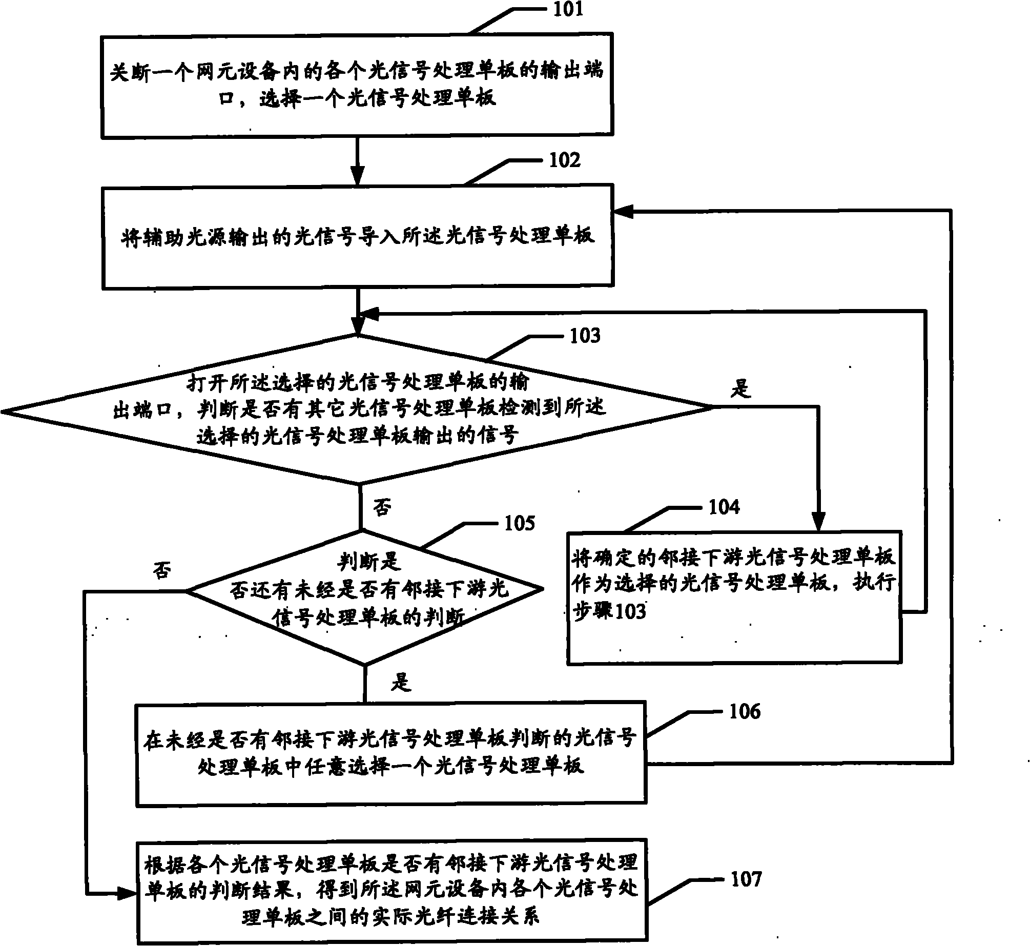
[0033] The basic flow of the method for checking the optical fiber connection relationship of the first embodiment of the present invention can be referred to figure 2 , The method for checking the optical fiber connection relationship of this embodiment mainly includes:

[0034] Step 101: Turn off the output port of each optical signal processing board in a network element device.

[0035] There is a switch in front of the output port of each optical signal processing board. This switch can control the closing of the output port of each optical signal processing board. If the output port of the optical signal processing board is opened, the received optical signal can be sent to its adjacent optical signal processing board after corresponding processing.

[0036] Step 102: Select an optical signal processing single board, and import the optical signal output by the auxiliary light source to the optical signal processing single board.

[0037] The auxiliary light source can output op...

Embodiment 2

[0048] The basic process of the method for checking the optical fiber connection relationship of the second embodiment of the present invention can be referred to Figure 4 , This embodiment combines image 3 The schematic diagram of the optical fiber connection of the network element equipment shown in this embodiment is illustrated by taking the case of discovering the connection relationship of the multiplexed fiber as an example. The method for checking the optical fiber connection relationship mainly includes:

[0049] Step 201, turn off image 3 For the output ports of each optical signal processing board in the network element device (ie, the output ports of U21, U22, U23, and U24), an optical signal processing board is selected arbitrarily, for example, the optical signal processing board U21 is selected.

[0050] Step 202: Import the optical signal output by the auxiliary light source from the input port of the optical signal processing board to the selected optical signal p...

no. 3 example

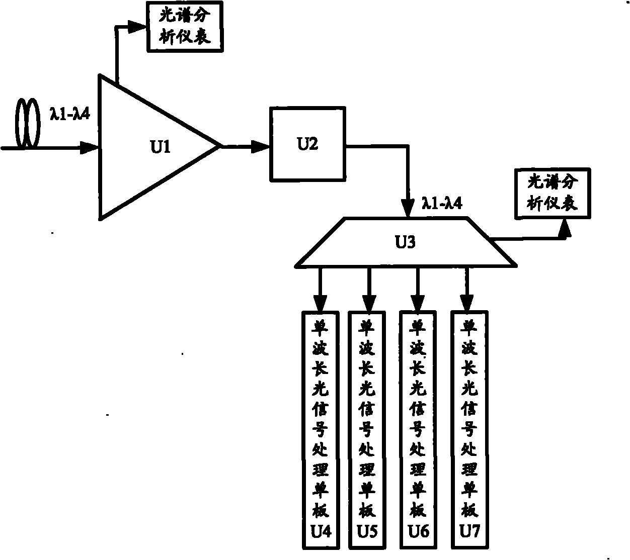
[0067] For ease of understanding, the method for checking the connection relationship of optical fibers provided by the present invention is described in detail below: this embodiment takes the checking of the connection relationship of a single-wave optical fiber as an example for description. See figure 1 , U3 is a single-wavelength signal processing board. The single-wavelength signal processing board U3 demultiplexes the received wavelength division multiplexed signal, and outputs single-wavelength signals from its output ports. Each output port of U3 is connected to one Single-wavelength optical signal processing board. See Figure 5 , Is a flowchart of the third embodiment of the method for checking optical fiber connection relationship provided by the present invention, and the method includes:

[0068] Step 301: Turn off the output port of each optical signal processing board in a network element device.

[0069] See figure 1 , Turn off the output ports of all boards. Ther...


PUM


Abstract

The embodiment of the invention provides an optical fiber connection relation checking method and an optical fiber connection relation checking device. In the method, light signals output by a secondary light source are controlled to be led into a selected light signal processing single board, an output port of the selected light signal processing single board is opened, and that whether other light signal processing single boards detect the light signals output by the selected light signal processing single board is judged, so that downstream light signal processing single boards adjacent tothe selected light signal processing single board are judged and the upstream and downstream connection relation between the light signal processing single boards is discovered by executing the stepsthrough the light signal processing single boards. Through the method and the device, the connection relation is checked without externally connected OSA instrument or built-in OSA unit, a new optical fiber connection error risk due to the introduction of new optical fiber connection is avoided, and the cost of the external OSA instrument or the built-in OSA unit cannot be increased.

Description

Technical field [0001] The invention relates to the field of communication technology, in particular to a method and device for checking optical fiber connection relations. Background technique [0002] With the development of communication technology, optical fiber technology has been used more and more widely. The optical fiber connection relationship inspection can ensure the quality of the system connection to a certain extent, reduce failure factors and find out the failure point of the optical fiber when it fails. [0003] In the prior art, the inspection method of the optical fiber connection relationship is realized by a built-in or external optical spectrum analysis (OSA) instrument in the optical signal processing single board, see figure 1 , Is a schematic diagram of the method of checking the connection relationship of the optical fiber in the prior art. The optical signal processing boards such as U1, U2, and U3 can be connected or built-in OSA meters or OSA spectrum an...

Claims


Application Information

Patent Timeline
Patent Type & Authority Applications(China)
IPC IPC(8): H04B10/08H04B10/12H04L12/26H04B10/07
Inventor 李泉黄伟刘伟
Owner 江苏联智科技服务有限公司
Why Eureka
Try Eureka