LED dimming control circuit

A dimming control circuit and control circuit technology, which are applied in energy-saving control technology, lamp circuit arrangement, light source and other directions, can solve the problems of complex realization process, etc., and achieve the effect of simple control method, convenient operation and energy saving.

Active Publication Date: 2010-11-24
OCEANS KING LIGHTING SCI&TECH CO LTD +1
View PDF0 Cites 54 Cited by
  • Summary
  • Abstract
  • Description
  • Claims
  • Application Information

AI Technical Summary

Problems solved by technology

However, in some application environments, the brightness of the LED light source is required to be manually adjustable. The traditional application circuit can only realize the adjustable brightness of

Method used


Image

  • LED dimming control circuit
  • LED dimming control circuit
  • LED dimming control circuit

Examples


Embodiment Construction

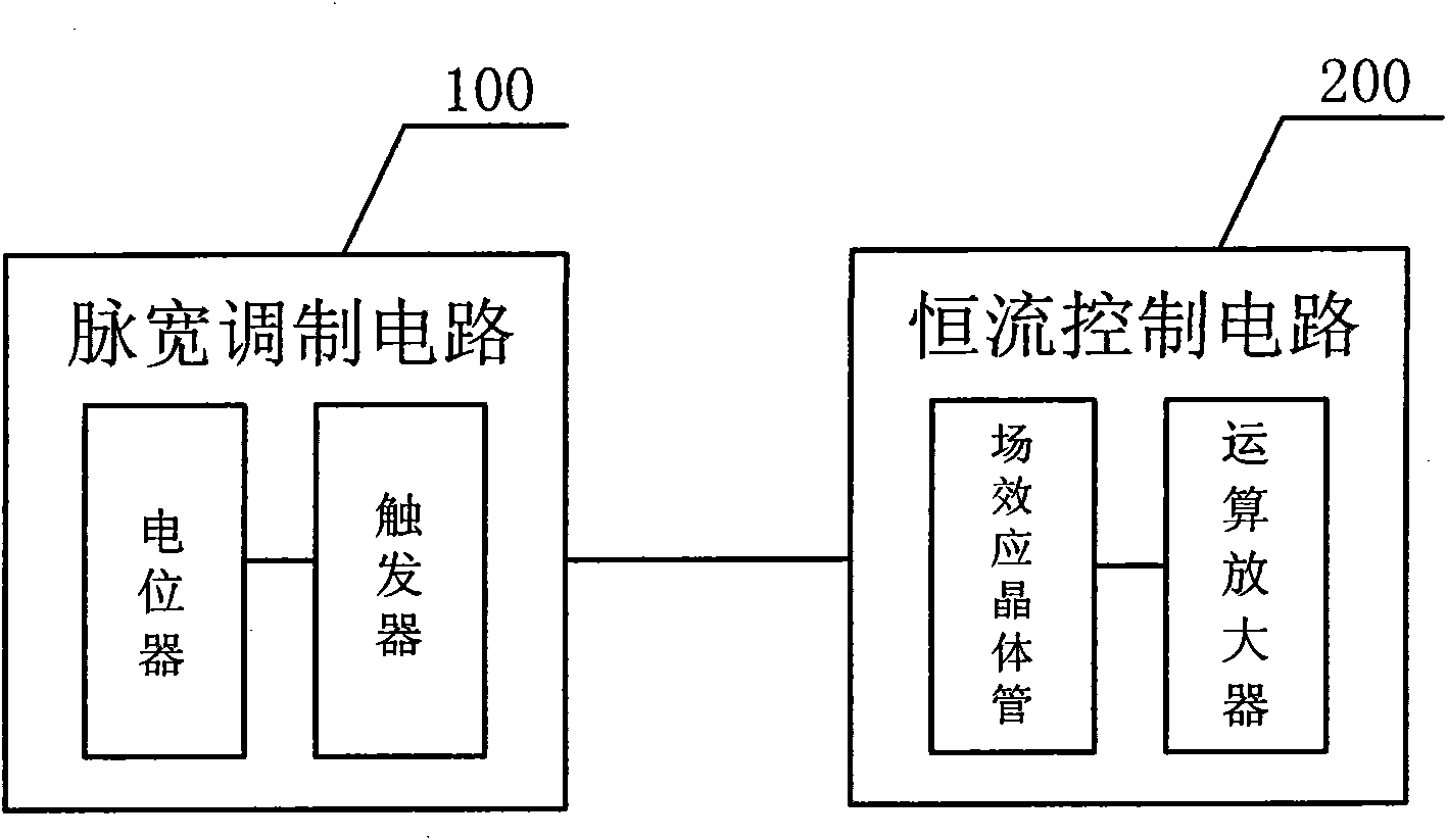
[0018] Such as figure 1 Shown is a schematic structural diagram of the LED dimming control circuit of the present invention. The LED dimming control circuit of the present invention includes a pulse width modulation circuit 100 and a constant current control circuit 200. The pulse width modulation circuit 100 includes a 555 trigger U2 and a potentiometer RW1, and the pulse width generated by the 555 trigger U2 is adjusted by adjusting the potentiometer RW1. The size of the constant current control circuit 200 includes a field effect transistor Q1, an operational amplifier U3A, and the pulse width generated by the 555 flip-flop U2 controls the off time of the field effect transistor Q1, and controls and changes the operation according to the off time of the field effect transistor Q1 The reference voltage potential of the amplifier U3A, and then adjust the size of the constant current.

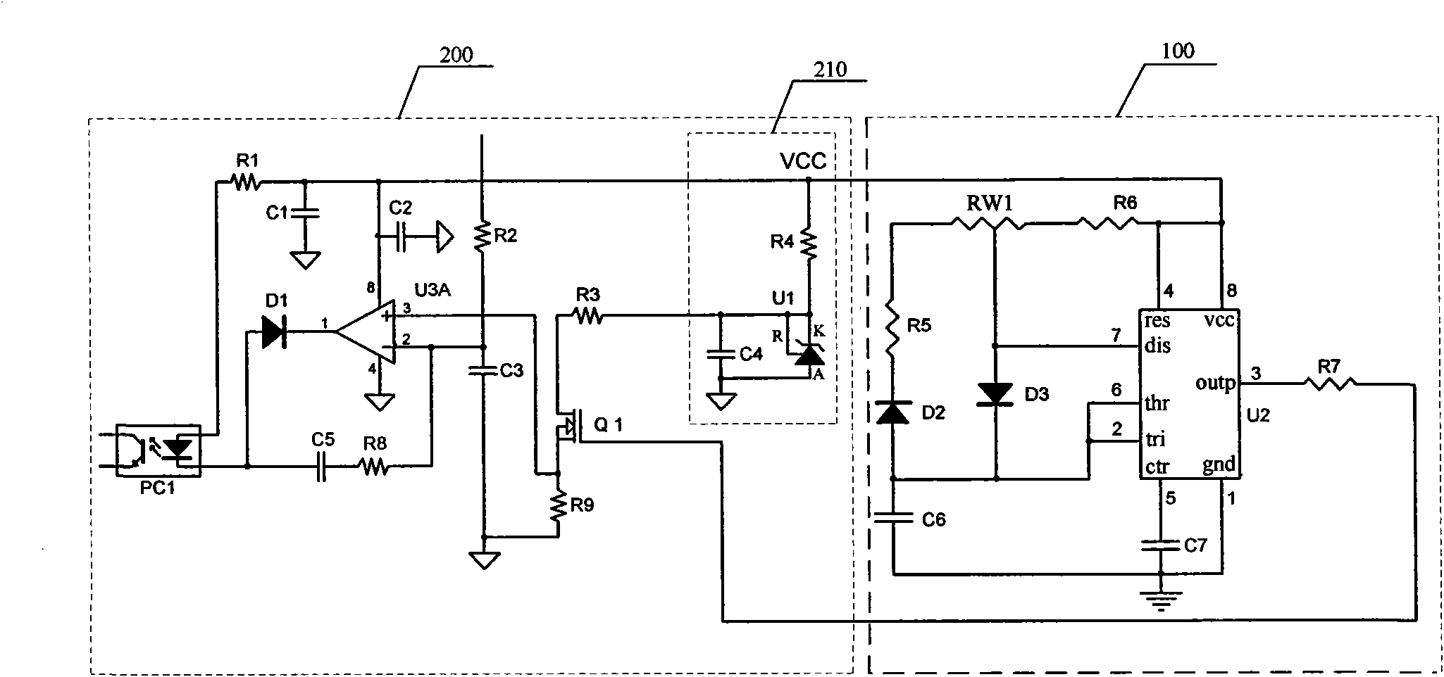
[0019] Such as figure 2 Shown is a schematic diagram of the LED dimming control circuit ...


PUM


Abstract

The invention relates to an LED dimming control circuit, which comprises a pulse width modulation control circuit (100) and a constant current control circuit (200). The pulse width modulation control circuit (100) comprises a trigger and a potentiometer; and the size of the pulse width generated by the trigger is adjusted by adjusting the potentiometer. The constant current control circuit (200) comprises a field effect transistor and an operational amplifier; and the pulse width generated by the trigger controls the on/off time of the field effect transistor, and controls the potential of reference voltage of the operational amplifier according to the on/off time of the field effect transistor so as to adjust the magnitude of constant current. In the LED dimming control circuit, the size of the pulse width generated by the trigger can be adjusted by adjusting the potentiometer manually, and the potential of the reference voltage of the operational amplifier is changed by setting the on/off time of the field effect transistor according to the size of the pulse width so as to adjust the magnitude of the constant current; therefore, the dimming function is realized.

Description

technical field [0001] The invention relates to the technical field of LED control, in particular to an LED dimming control circuit. Background technique [0002] LED light sources have the characteristics of high luminous efficiency, uniform spectral distribution, high efficiency and energy saving, long life, and low-voltage controllability. They are widely used in urban greening lighting, mine lights, flashlights, motor vehicles, indoor and outdoor lighting and other fields. However, in some application environments, the brightness of the LED light source is required to be manually adjustable. The traditional application circuit can only realize the adjustable brightness of the LED light source by replacing the resistor device in the control circuit. The realization process is complicated and cannot well meet people's daily life. Simple and convenient manual dimming needs. Contents of the invention [0003] The technical problem to be solved by the present invention is ...

Claims


Application Information

Patent Timeline
IPC IPC(8): H05B37/02
CPCY02B20/42Y02B20/40
Inventor 周明杰陈清桥
Owner OCEANS KING LIGHTING SCI&TECH CO LTD
Why Eureka
Try Eureka