Method for the production of an integrally bladed rotor, and rotor

A technology of integral installation and rotor, which is applied in the direction of supporting elements of blades, manufacturing tools, engine manufacturing, etc., can solve expensive problems and achieve the effect of reducing structural volume and reducing structural volume

Inactive Publication Date: 2010-11-24
MTU AERO ENGINES GMBH
View PDF0 Cites 5 Cited by
  • Summary
  • Abstract
  • Description
  • Claims
  • Application Information

AI Technical Summary

Problems solved by technology

[0003] It is known from the prior art that gas turbine rotors with integrally mounted blades are produced in one piece by milling, which is of course very labor-intensive and expensive, so that this method is only suitable for relatively small gas turbine rotors

Method used


Image

  • Method for the production of an integrally bladed rotor, and rotor
  • Method for the production of an integrally bladed rotor, and rotor

Examples


Embodiment Construction

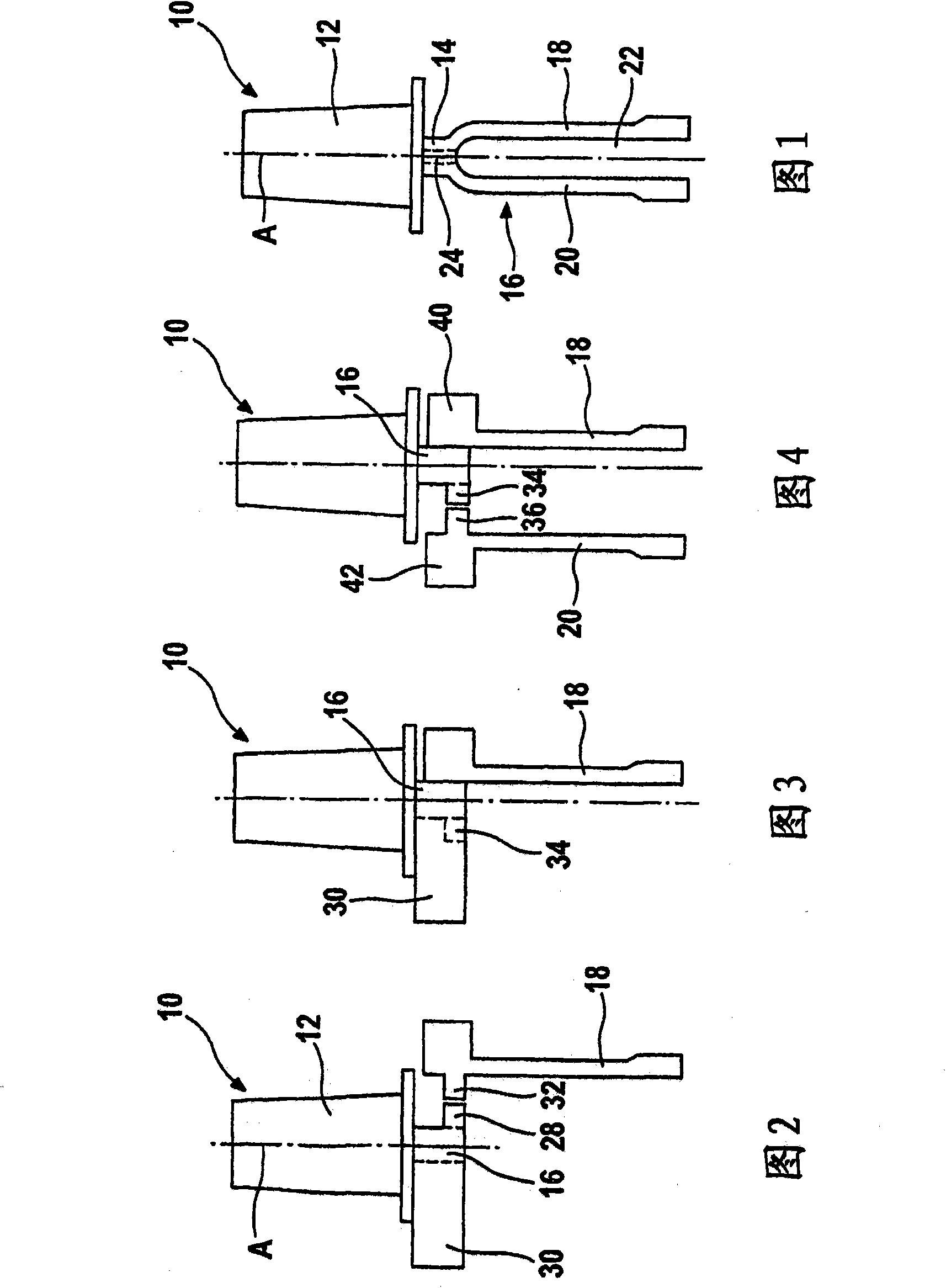
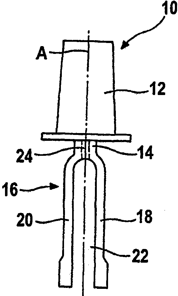
[0028] exist figure 1 An integrally bladed rotor in the form of a gas turbine rotor is shown in half-section in .

[0029] The rotor comprises segments, namely a cascade ring 10 with turbine blades 12 and a ring segment 14 connecting the turbine blades 12 and a rotor carrier.

[0030] The rotor carrier includes a first rotor base body 18 and a second rotor base body 20 . The two rotor base bodies 18 , 20 are fastened to the cascade ring 10 by friction welding.

[0031] as from figure 1 As can be seen, the rotor base bodies 18 , 20 are axially spaced apart from each other, thereby forming a cavity 22 therebetween, which may be part of a cooling channel system that reaches the turbine via some further channels 24 Blade 12.

[0032] The manufacture of the rotor is explained below. Cascade ring 10 is manufactured such that turbine blades 12 are mounted on ring segments 16 by welding, brazing or casting the ring segments. The ring segments 16 are typically made of a differe...


PUM


Abstract

Disclosed is a method for producing an integrally bladed rotor, in which the rotor support is composed of several disk-type rotor bases (18, 20) that are welded onto the blade ring (10).

Description

technical field [0001] The present invention relates to a method for manufacturing an integrally bladed rotor, in particular a gas turbine rotor, and the rotor itself. Background technique [0002] A gas turbine rotor with integrally mounted blades is called a Blisk or Bling, depending on whether there is a rotor or rotor support with a disc-shaped or annular cross-section (hereinafter referred to as the rotor base) . Leaf disc is the abbreviation of disc with blades, and leaf ring is the abbreviation of ring with blades. [0003] It is known from the prior art that gas turbine rotors with integrally mounted blades are produced in one piece by milling, which is of course very complex and expensive, so this method is only suitable for relatively small gas turbine rotors. [0004] An additional method used in large rotors is friction welding. In this case, the rotor base body and the blades are produced separately and then friction welded to each other, in particular by lin...

Claims


Application Information

Patent Timeline
Patent Type & Authority Applications(China)
IPC IPC(8): B23P15/00B23K20/12F01D5/34
CPCB23K20/12F01D5/34B23K2201/001B23P15/006F05B2230/239B23K2101/001
Inventor E·拜尔
Owner MTU AERO ENGINES GMBH
Why Eureka
Try Eureka