Laminated iron core for rotor

A rotor and iron core technology, which is applied in the field of rotor laminated iron cores, can solve the problems that the thickness of the connecting part 78 is no longer constant, difficult to control, and the thickness is increased, so as to achieve the effects of easy quality management, preventing deformation and improving the quality of the motor.

Inactive Publication Date: 2010-11-24
YASKAWA DENKI KK
View PDF2 Cites 6 Cited by
  • Summary
  • Abstract
  • Description
  • Claims
  • Application Information

AI Technical Summary

Problems solved by technology

[0008] However, in the technology described in Patent Document 1, when the connection portion 78 is bent, the stress is transmitted to the permanent magnet holding protrusion 73, and the radially outer end portion of the permanent magnet holding protrusion 73 is pulled in the circumferential direction, resulting in Both sides of the permanent magnet accommodating part 75 are opened, thereby causing a problem that the permanent magnet cannot be accurately joined.
Of course, the shape of the linear permanent magnet holding protruding portion 73 can also be determined in consideration of the amount of deformation, but since the deformation of the permanent magnet holding protruding portion 73 changes according to the physical properties of the material, it is difficult to accurately control it.
[0009] Moreover, when the connecting portion 78 is bent, the radially outer side of the connecting portion 78 expands and the radially inner side shrinks. As a result, the thickness of the connecting portion 78 is no longer constant, and its thickness increases on the radially inner side of the connecting portion 78. When pressing many core pieces, the thickness of the rotor laminated core is no longer uniform
[0010] This problem is also a common problem in the technology described in Patent Document 2

Method used


Image

  • Laminated iron core for rotor
  • Laminated iron core for rotor
  • Laminated iron core for rotor

Examples


Embodiment Construction

[0037] Next, specific embodiments of the present invention will be described with reference to the drawings to facilitate understanding of the present invention.

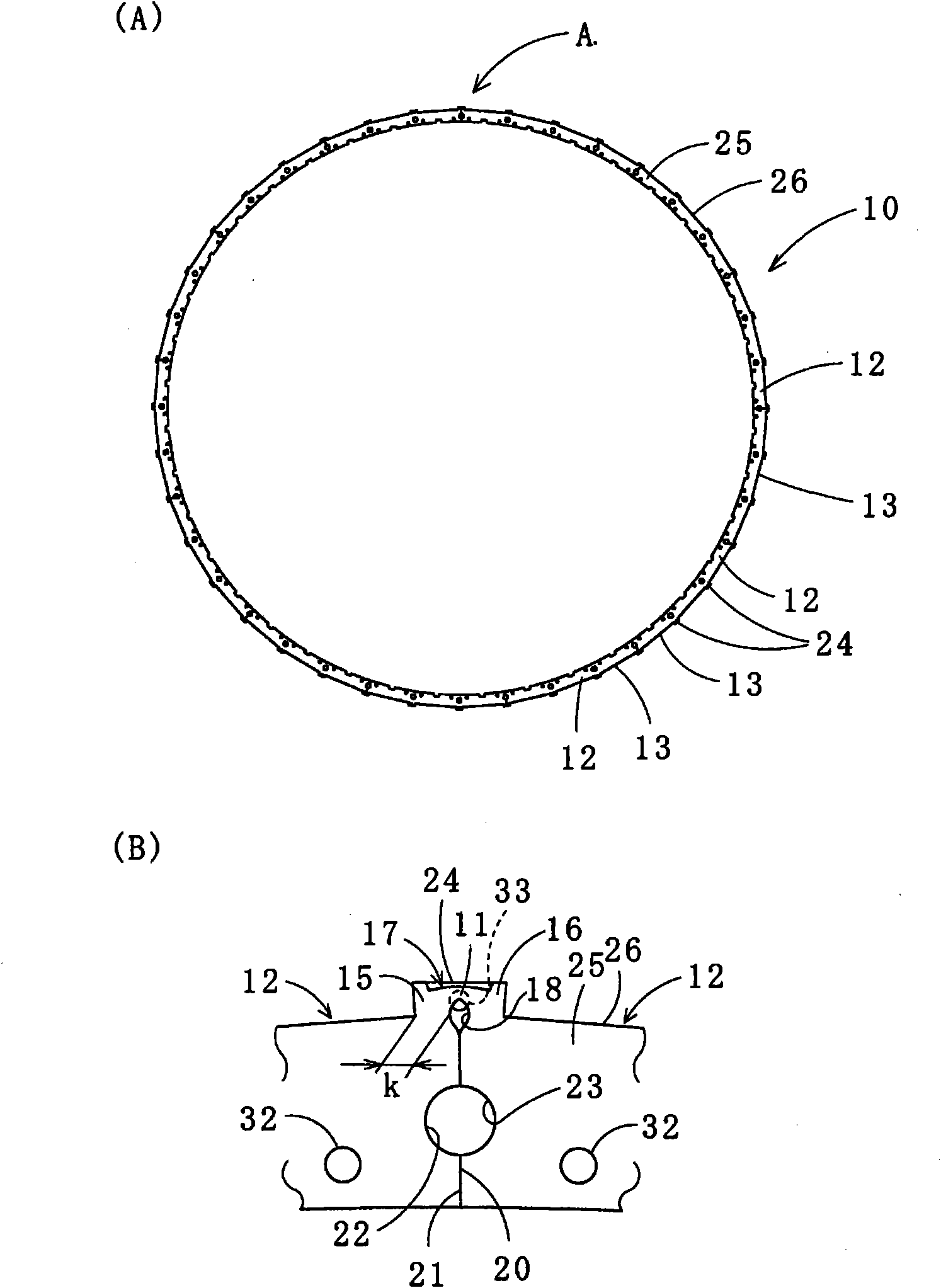
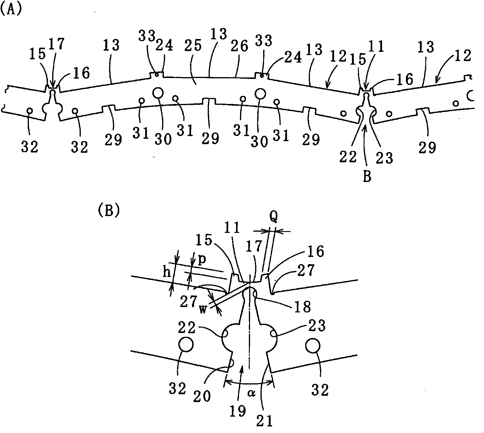
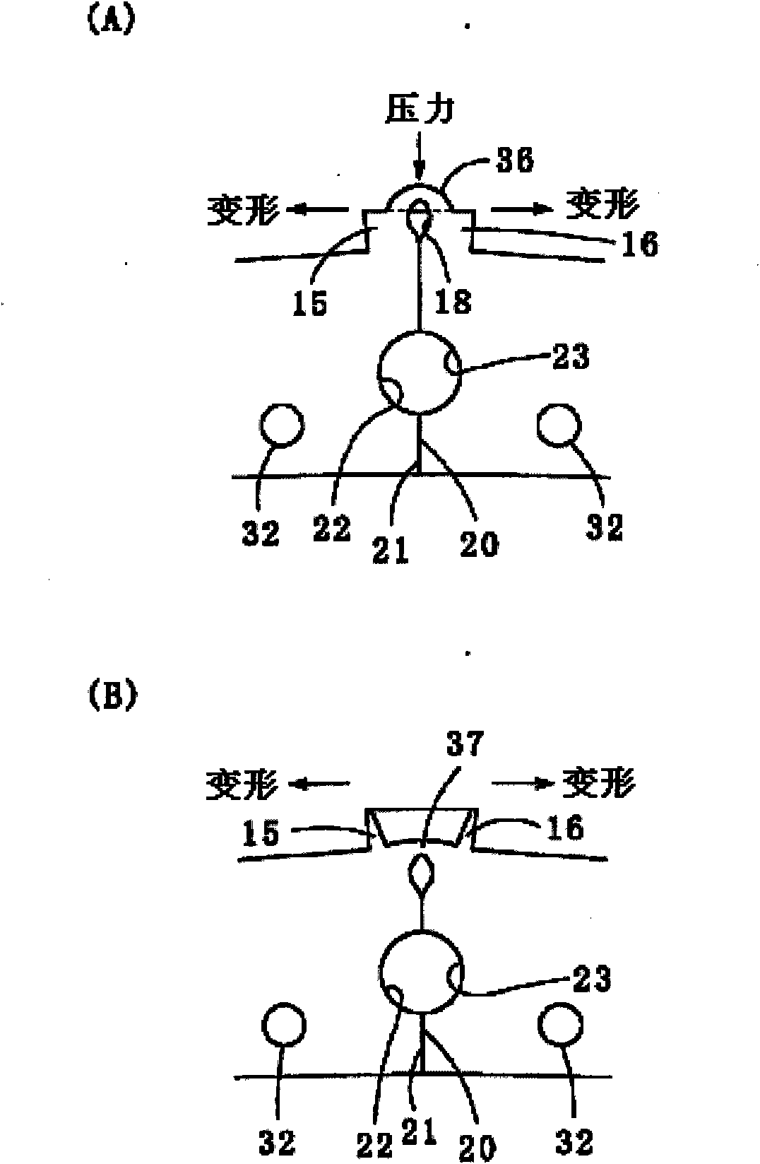
[0038] here, figure 1 (A) is a plan view of a rotor laminated core according to an embodiment of the present invention, and (B) is an enlarged view of arrow A; figure 2 (A) is a partial top view of the band-shaped sector-shaped core pieces connected by the connecting part, and (B) is an enlarged view of the arrow B part; image 3 (A) and (B) are detailed diagrams of the connecting portion of the sector-shaped core pieces of the comparative example; Figure 4 It is a detailed plan view around the connection part.

[0039] like figure 1 (A), (B), figure 2 As shown, the rotor laminated core 10 according to one embodiment of the present invention is a member in which a plurality of arc-shaped sector core pieces 12 connected by connecting portions 11 are laminated by spiral winding. The whole has 40 poles, that ...


PUM


Abstract

Provided is a laminated iron core for a rotor, in which a permanent magnet holding portion for fixing a permanent magnet on the radially outer side is fixed in shape and can hold the permanent magnet precisely thereon and which is prevented from having such an uneven thickness thereof as might otherwise be caused by a bulge in the thickness direction at an iron core member folding time. Adjoining segment iron core members (12) are equipped at their confronting end faces with permanent magnet holding protrusions (15, 16) having connecting portions (11) at their centers. Permanent magnet holding protrusions (24) of the upper and lower segment iron core members (12) overlapping the permanent magnet holding protrusions (15, 16) to have the connecting portions (11) formed therein are equipped with housings (33), in which the bulging portions formed in the thickness direction at the time of folding the connecting portions (11) are fitted.

Description

technical field [0001] The present invention relates to a laminated iron core for use in a rotor of a permanent magnet type rotating electric machine, in which a plurality of permanent magnets are arranged on the outside in the radial direction, and more particularly relates to a plurality of sector-shaped iron cores which are spirally wound and laminated and continuous in a band shape Rotor laminated core manufactured from sheet. Background technique [0002] In drive motors, in order to achieve energy saving, high output, high efficiency, etc., a so-called rotor with magnets is used, in which magnet blocks are attached to a laminated rotor core. This laminated rotor core is manufactured by punching out a magnetic metal plate to form annular rotor core pieces usually using a die apparatus, laminating a predetermined number of the rotor core pieces, and riveting and laminating each other. According to this method of manufacturing a laminated rotor core, a laminated rotor co...

Claims


Application Information

Patent Timeline
Patent Type & Authority Applications(China)
IPC IPC(8): H02K1/22H02K1/27
CPCH02K1/278
Inventor 津曲宏明神巌
Owner YASKAWA DENKI KK
Why Eureka
Try Eureka