Image encoding method and image encoding device

一种图像编码、图片编码的技术,应用在图像通信、电视、电气元件等方向,能够解决成为问题、初始化处理多、难比特数编码控制等问题

Active Publication Date: 2010-11-24
PANASONIC CORP
View PDF0 Cites 3 Cited by
  • Summary
  • Abstract
  • Description
  • Claims
  • Application Information

AI Technical Summary

Problems solved by technology

This is particularly a problem in coding that requires a lot of initialization processing of variables at the front end of the slice, such as arithmetic coding used in H.264, which has a very high compression rate.
[0053] 2) The code amount of the slice header (common data required for decoding the macroblock contained in the slice) increases and the compression efficiency deteriorates
Therefore, if Figure 9B As shown in picture N+4 and picture N+5, especially in the case of continuously encoding I slices that generate a large number of bits, it is difficult to perform encoding control to make the number of bits constant, and it cannot be well controlled to the desired number of bits. number of bits
Therefore, the number of dominant bits cannot be constant, or if the number of bits is forced to be constant, large image quality degradation will occur

Method used


Image

  • Image encoding method and image encoding device
  • Image encoding method and image encoding device
  • Image encoding method and image encoding device

Examples


Embodiment approach 1

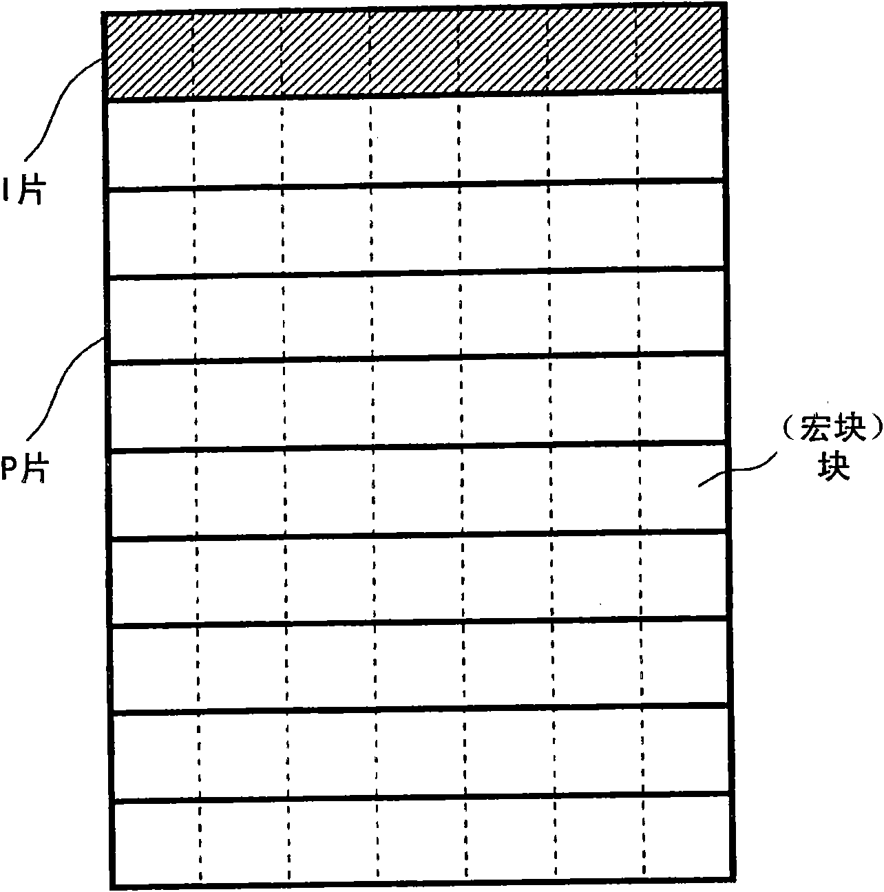
[0221] Picture 11 It is a figure explaining the relationship between a slice and a block in the case of using the slice dividing method of Embodiment 1 of this invention. Picture 11 The picture (1 frame) shown is composed of multiple blocks. Among the blocks constituting the picture, the areas of the blocks with diagonal lines are slices and are I slices. The multiple blocks surrounded by other thick lines are slices and are P slices. Here, an example in which a picture is composed of I slices and P slices is shown. figure 1 The difference between the slice division method of the MPEG-2 standard and the slice division method of the present invention is that the number of blocks contained in the I slice is smaller than the number of blocks contained in the P slice (the slice size is smaller).

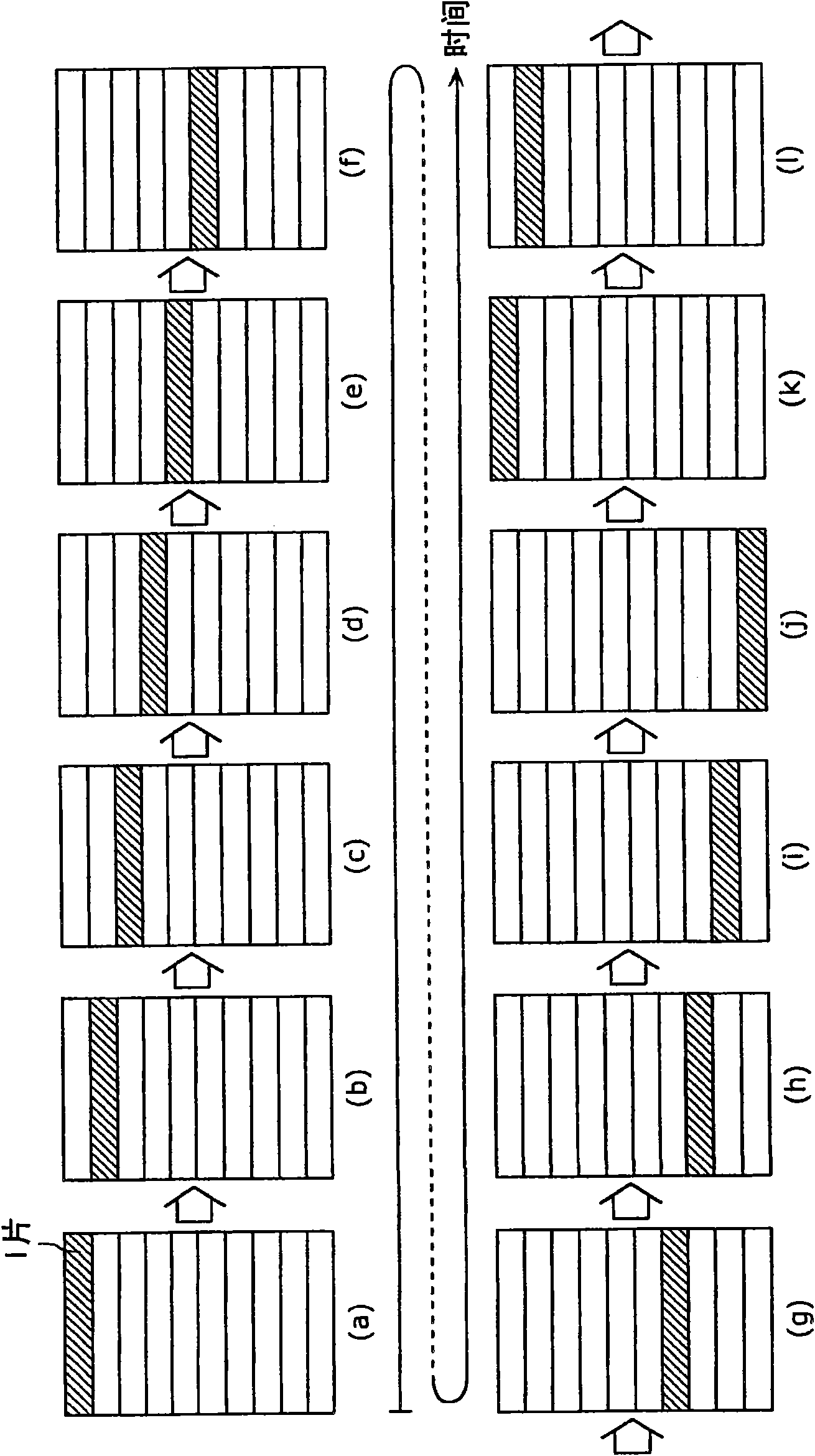
[0222] Picture 12 It is a diagram showing an example of the slice division of pictures that are consecutive in time order in Embodiment 1 of the present invention. Here, the slashed sli...

Embodiment approach 2

[0251] Next, the second embodiment will be described below. The description of the same structure and the same operation as in Embodiment 1 is omitted.

[0252] Figure 15 It is a diagram showing an example of the slice division of pictures that are consecutive in time order in Embodiment 2 of the present invention. Here, the slashed slices are I slices, and the other slices are P slices. Picture 12 The slice division method of Embodiment 1 in Figure 15 The difference between the slice division method of the second embodiment in this embodiment is that the size of the P slice immediately after the I slice is constant (N blocks), and the boundary position (slice division position) of the P slice below the I slice is shifted down by one The number of rows of the slice.

[0253] Therefore, in the second embodiment, the feature is that the number of slices constituting a picture is smaller than that in the first embodiment. For example, compare Picture 12 with Figure 15 . If com...

Embodiment approach 3

[0257] Next, the third embodiment will be described below. The description of the same structure and the same operation as those of Embodiments 1 and 2 is omitted.

[0258] Figure 17 It is a diagram showing an example of the slice division of pictures that are consecutive in time order according to Embodiment 3 of the present invention. Here, the slashed slices are I slices, and the other slices are P slices.

[0259] In the first embodiment, except for the pictures between the pictures with I slices on the bottom row and the pictures with I slices on the top row, all pictures include I slices. In this third embodiment, assuming that the network quality is high, the insertion frequency of I slices can also be less. In this case, such as Figure 17 As shown, pictures that do not contain I slices are inserted regularly.

[0260] However, it is known that in the case of reproducing a stream, it is generally best to insert more than one I picture in the stream for 2 seconds. For exa...


PUM


Abstract

Disclosed is an image encoding device that can lower the stream disappearance frequency, reduce the amount of processing and improve the compression rate without hindering pipelining or paralleling. Said image encoding device is equipped with a dividing means, which divides a picture into an I slice composed of plural blocks and a P slice composed of plural blocks, and an encoding means, which encodes plural pictures that are chronologically consecutive by successively encoding each slice in block units. The dividing means changes the position of the I slice in each of the plural pictures that are chronologically consecutive so that the positions of the I slices in said plural pictures circulate for a fixed number of pictures among the plural pictures that are chronologically consecutive, and divides each of the plural pictures that are chronologically consecutive so that the sum of the number of blocks included in an I slice and the number of blocks included in one or more P slices between said I slice and the next I slice has a prescribed value.

Description

Technical field [0001] The present invention relates to an image coding method and an image coding device. In particular, it relates to image coding in which the image signal is divided into slices composed of a plurality of blocks according to the MPEG (Moving Picture Experts Group)-4 AVC method or the ITU-T H.264 method, and each slice is coded on a block basis. Method and image coding device. Background technique [0002] In recent years, we have ushered in the multimedia era that comprehensively processes sound, image, and other pixel values. Information media such as news, magazines, television, radio, and telephone can be transmitted to human devices as multimedia objects. adoption. Generally, the so-called multimedia not only refers to text, but also refers to the simultaneous representation of graphics, sounds, and especially images. In order to make the above-mentioned existing information media an object of multimedia, it is necessary to express the information in di...

Claims


Application Information

Patent Timeline
Patent Type & Authority Applications(China)
IPC IPC(8): H04N7/32H04N19/50H04N19/107H04N19/134H04N19/174H04N19/189H04N19/196H04N19/503H04N19/51H04N19/65
CPCH04N19/00781H04N19/00272H04N19/0003H04N19/107H04N19/174H04N19/61
Inventor 角野真也
Owner PANASONIC CORP
Why Eureka
Try Eureka