Active variable-stiffness leveling pile and construction method thereof

A construction method and variable stiffness technology, applied in sheet pile wall, foundation structure engineering, construction, etc., can solve problems such as reducing pile cost, foundation and superstructure affecting structural safety, etc., to reduce cost, eliminate potential safety hazards, reduce added effect

Active Publication Date: 2011-08-24
姚攀峰
View PDF0 Cites 0 Cited by
  • Summary
  • Abstract
  • Description
  • Claims
  • Application Information

AI Technical Summary

Problems solved by technology

[0004] The purpose of the present invention is to provide an active variable stiffness leveling pile and its construction method, to solve the technical problem that the secondary stress of the foundation and superstructure due to the uneven settlement of the pile body affects the structural safety; and solve the problem of using the bearing capacity of the foundation The Problem of Reducing the Cost of Pile Body

Method used


Image

  • Active variable-stiffness leveling pile and construction method thereof
  • Active variable-stiffness leveling pile and construction method thereof
  • Active variable-stiffness leveling pile and construction method thereof

Examples


Embodiment 1

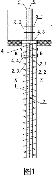
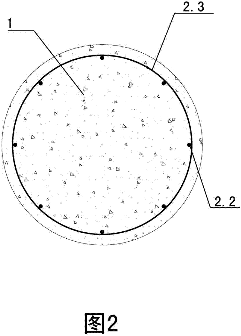
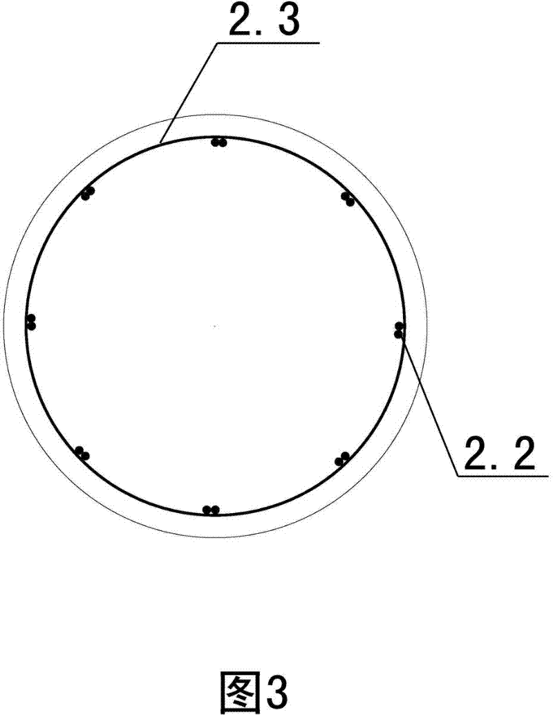
[0066] Embodiment one sees Figure 1 ~ Figure 4 and Figure 30-32 As shown, an active variable stiffness leveling pile is located at the bottom of the foundation 8, and is formed by cast-in-situ pile body reinforcement cage 2 and pile body concrete 1 welded by transverse reinforcement 2.1, longitudinal reinforcement 2.2 and pile stirrup 2.3 , also includes the leveling section, the leveling section is located on the top of the reinforced concrete pile body, including the leveling steel cage 3, the leveling tube 4, the exhaust pipe 5, the pouring tube 6 and the post-cast concrete 7, and the leveling tube 4 is set on the steel bar The upper part of the concrete pile body is composed of the cylinder wall 4.1 and the partition plate. The leveling reinforcement cage 3 is located on the top of the leveling cylinder 4 and is integrated with the foundation 8. It has a built-in exhaust pipe 5 and pouring pipe 6 to level the longitudinal reinforcement. 3.2 and the pouring pipe 6 extend...

Embodiment 2

[0079] Embodiment two see Figure 27 ~ Figure 29 , on the basis of the above-mentioned construction method, the first step is to carry out mud wall protection while forming the hole.

[0080] In the second step, the welded pile reinforcement cage 2 is inserted into the post-casting equipment 11; in the third step, the post-grouting layer 12 is poured by the post-casting equipment 11 when pouring the concrete for the pile body.

[0081] The hole forming method in Step 1 described in the above-mentioned embodiments 1 and 2 is manual digging, rotary drilling, impact hole forming or grab bucket hole forming.


PUM


Abstract

The invention relates to an active variable-stiffness leveling pile and a construction method thereof. A filling pile, on the basis of a reinforced concrete pile body, is provided with a leveling section which is positioned on the upper part of the reinforced concrete pile body and comprises a leveling steel reinforcement cage, a leveling cylinder, an exhaust pipe, a pouring pipe and after-pouring concrete, wherein the leveling cylinder is sleeved on the upper part of the reinforced concrete pile body and consists of a cylinder wall and a clapboard; the leveling steel reinforcement cage is positioned at top of the leveling cylinder and is cast-in-place with a foundation to form a whole body, the exhaust pipe and the pouring pipe are arranged in the leveling steel reinforcement cage; and aleveling longitudinal bar and the pouring pipe extend into the leveling cylinder and are lapped with a longitudinal reinforcing steel bar of the pile, and is cast-in-place with the leveling cylinder,the upper pile body steel reinforcement cage and the after-pouring concrete. The active variable-stiffness leveling pile and the construction method thereof solve the problem that the differential settlement of the pile body under the action of the dead weight of the upper structure causes pile group top surfaces are not at the same horizontal position, and are suitable for the construction of the pile body of the filling pile.

Description

technical field [0001] The invention relates to a pouring pile and a construction method thereof, in particular to an active variable stiffness leveling pile and a construction method thereof. Background technique [0002] The cast-in-situ pile system refers to the piles formed by forming pile holes in the foundation soil by means of mechanical drilling, steel pipe extrusion or manual excavation on the project site, and placing steel cages in them and pouring concrete. Cast-in-place piles were first established in 1893, more than 100 years ago. Due to the development of industry and population growth, high-rise buildings continued to increase. However, because the foundation conditions of many cities were relatively poor, they could not directly bear the pressure from high-rise buildings. Below the surface There is a thick layer of soft soil or medium-strength clay, and if the friction piles commonly used at that time are still used in the construction of high-rise buildings...

Claims


Application Information

Patent Timeline
Patent Type & Authority Patents(China)
IPC IPC(8): E02D5/34E02D5/38E02D5/62E02D5/66
Inventor 姚攀峰
Owner 姚攀峰
Why Eureka
Try Eureka